Sunday, January 18, 2009
Quick Tip - A Shortcut for Closing Active Drawing
You already know that ALT+F4 can effectively be used to quit a running application in windows operating system. For those who don't know, pressing CTRL+F4 inside AutoCAD will close the active drawing without touching the application or other drawings already open over there. Though it's a more straight forward shortcut than the ALT+F+C, I would like to stick to the latter as it looks easier to me (May be because I am used to that). CTRL+F4 shortcut is not limited to AutoCAD, but it works well with almost all windows multi document interface (MDI) applications.

Sunday, January 4, 2009
My New Year Wish - An Intermediate AutoCAD Product for 2D Designing & Draughting
Why? Let's have a look at the existing product line. ie, Vanilla AutoCAD and AutoCAD LT. You might be able to find an answer from there.
AutoCAD LT: The lack of strong application programming interfaces makes AutoCAD LT really handicapped in the perspective of a Power User or CAD Administrator. You can not use any of your custom commands developed using AutoLISP/VBA/Dotnet/ObjectARX inside LT. The remaining option called DIESEL is only good enough to make small macros. Not only that; the number of commands are limited as compared to the full version.
Vanilla AutoCAD: Very powerful platform for 2D as well as 3D designing and modeling. The disadvantage is that it's loaded with comprehensive 3D modeling and rendering engines which are not at all used by the 2D user. Believe me; I have never used any of the 3D modeling or rendering features for the past 4 or 5 years for official purpose. That means the 2D users are carrying a burden over their shoulders and have been quite unnecessarily paying for the unwanted features. They could work much faster, if all those unwanted features were not loaded over there. The recent versions of AutoCAD show that it is more inclined towards 3D development than the 2D ones.
The need of the moment is an intermediate AutoCAD Product, which offers the power of Vanilla AutoCAD customization and 2D features minus all the 3D/rendering features with an attractive price tag. In that case, managers don't have to think twice at the time of purchase/upgrade of the product as they normally would do. As of now, we are forced to use Vanilla AutoCAD as we have in-house discipline specific menus and associated programs.
I am sorry to have started the New Year in a rebellion mood. But we really wish to see such a product available in the industry. Please note that the above views and opinions are my personal ones and those don't reflect the views or policies of the company I am working for. I take this opportunity to wish you a happy and prosperous new year. May the New Year make our dreams (including the CAD related ones ;-) come true...!! Many thanks to all you people for visiting my blog.
AutoCAD LT: The lack of strong application programming interfaces makes AutoCAD LT really handicapped in the perspective of a Power User or CAD Administrator. You can not use any of your custom commands developed using AutoLISP/VBA/Dotnet/ObjectARX inside LT. The remaining option called DIESEL is only good enough to make small macros. Not only that; the number of commands are limited as compared to the full version.
Vanilla AutoCAD: Very powerful platform for 2D as well as 3D designing and modeling. The disadvantage is that it's loaded with comprehensive 3D modeling and rendering engines which are not at all used by the 2D user. Believe me; I have never used any of the 3D modeling or rendering features for the past 4 or 5 years for official purpose. That means the 2D users are carrying a burden over their shoulders and have been quite unnecessarily paying for the unwanted features. They could work much faster, if all those unwanted features were not loaded over there. The recent versions of AutoCAD show that it is more inclined towards 3D development than the 2D ones.
The need of the moment is an intermediate AutoCAD Product, which offers the power of Vanilla AutoCAD customization and 2D features minus all the 3D/rendering features with an attractive price tag. In that case, managers don't have to think twice at the time of purchase/upgrade of the product as they normally would do. As of now, we are forced to use Vanilla AutoCAD as we have in-house discipline specific menus and associated programs.
I am sorry to have started the New Year in a rebellion mood. But we really wish to see such a product available in the industry. Please note that the above views and opinions are my personal ones and those don't reflect the views or policies of the company I am working for. I take this opportunity to wish you a happy and prosperous new year. May the New Year make our dreams (including the CAD related ones ;-) come true...!! Many thanks to all you people for visiting my blog.
Wednesday, November 19, 2008
Developing a Sine Wave Generator using DIECAL
In the last post, we saw how easiy we could accomplish complicated operations using DIECAL. Further to that, we are going develop a sine wave generator using a few lines of code. I know that you don't have a sine wave generator even in your wildest DIESEL dreams. But it is a really simple task using DIECAL. Once again, I am going to use points in order to make it simple. For generating sine wave, use the following macro.
*^C^C_setvar;userr1;$M=$(+,$(getvar,userr1),$(getvar,userr2))$(if,$(>=,$(*,$(+,$(getvar,userr1),$(getvar,userr2)),10),$(*,$(getvar,userr3),360)),^C)_Point;'CAL;[$(getvar,userr4)+$(+,$(getvar,userr1),$(getvar,userr2))/18,sin(10*$(+,$(getvar,userr1),$(getvar,userr2)))];
The above macro makes use of USERR1 to USERR4 system variables. The USERR1 and USERR2 values are automatically set by the set/reset macro (given below). USERR3 holds the value for number of cycles created and USERR4 is for X axis lag value (See the sample image). Use the following macro to set/reset initial values. When you run this macro, just follow the status bar messages.
^C^C_setvar;userr1;-1;;userr2;1;userr3;1;_modemacro;Enter number of cycles:;userr3;\userr4;0;_modemacro;Enter lag value for X axis:;setvar;userr4;\_modemacro;.;
The following image illustrates three sine waves gererated with a cycle value of 3 and X axis lag value 0 (Red) .22 (Green) and .44(Yellow).

*^C^C_setvar;userr1;$M=$(+,$(getvar,userr1),$(getvar,userr2))$(if,$(>=,$(*,$(+,$(getvar,userr1),$(getvar,userr2)),10),$(*,$(getvar,userr3),360)),^C)_Point;'CAL;[$(getvar,userr4)+$(+,$(getvar,userr1),$(getvar,userr2))/18,sin(10*$(+,$(getvar,userr1),$(getvar,userr2)))];
The above macro makes use of USERR1 to USERR4 system variables. The USERR1 and USERR2 values are automatically set by the set/reset macro (given below). USERR3 holds the value for number of cycles created and USERR4 is for X axis lag value (See the sample image). Use the following macro to set/reset initial values. When you run this macro, just follow the status bar messages.
^C^C_setvar;userr1;-1;;userr2;1;userr3;1;_modemacro;Enter number of cycles:;userr3;\userr4;0;_modemacro;Enter lag value for X axis:;setvar;userr4;\_modemacro;.;
The following image illustrates three sine waves gererated with a cycle value of 3 and X axis lag value 0 (Red) .22 (Green) and .44(Yellow).

Thursday, November 13, 2008
DIECAL - It's DIESEL Enhanced with a Mathematical Engine
In the last post I mentioned that I could come up with some better posts after the vacation, with the help of a refreshed mind. Hope this post justifies my words.
The absence of a strong mathematical engine inside DIESEL has troubled most of us in the past. We are going to overcome this limitation by mixing up DIESEL with the command line calculater. It should work in AutoCAD LT as command line calculator has been included in LT2009.If you compare, DIECAL capabilities are far better than DIESEL. Using DIECAL, you can do vector calculations, access various numeric functions which are not available in DIESEL and can do so many other things. If you are not convinced, here is a sample macro to draw a sphere by placing points across the surface of a sphere.
*^C^Csetvar;userr1;$M=$(+,$(getvar,userr1),$(getvar,userr4));$(if,$(>=,$(getvar,userr1),360),setvar;userr2;$
(+,$(getvar,userr2),$(getvar,userr5));setvar;userr1;0;)_Point;'CAL;[$(getvar,userr3)
<$(+,$(getvar,userr1),$(getvar,userr4))<$(getvar,userr2)];$(if,$(>,$(getvar,userr2),270),^c)
This macro uses USERR1 to USERR5 system variables to store values. The USERR1 and USERR2 system variable values are handled by the above macro. The USERR3 system variable stores the radius of the sphere, USERR4 holds the angle between the horizontal points and USERR5 holds the angle between vertical points. These values can be set/reset using the following macro. When you run this macro, just follow the instructions shown in the status bar.
^C^C_setvar;userr1;0;;userr2;90;_modemacro;Enter sphere radius:;userr3;\_modemacro;Enter angle between horizontal points:;userr4;\_modemacro;Enter angle between vertical points:;userr5;\_modemacro;.;
Please remember to run this macro to set/reset values before using the main macro.The first macro makes use of the Spherical Coordinate System point format entry to place points across the surface of the sphere.Please note that the CAL command has to be invoked transparently ('CAL) in the macro in order to output the result of calculation to the active command. It's my lack of knowledge in mathematics that prevents me from showing off a powerful application to exihibit the true potential of DIECAL. Those who know trigonometry and vector algebra will really enjoy this method. Following are some sample spheres made using different radius and angle values.

Point Sphere - Top View
The absence of a strong mathematical engine inside DIESEL has troubled most of us in the past. We are going to overcome this limitation by mixing up DIESEL with the command line calculater. It should work in AutoCAD LT as command line calculator has been included in LT2009.If you compare, DIECAL capabilities are far better than DIESEL. Using DIECAL, you can do vector calculations, access various numeric functions which are not available in DIESEL and can do so many other things. If you are not convinced, here is a sample macro to draw a sphere by placing points across the surface of a sphere.
*^C^Csetvar;userr1;$M=$(+,$(getvar,userr1),$(getvar,userr4));$(if,$(>=,$(getvar,userr1),360),setvar;userr2;$
(+,$(getvar,userr2),$(getvar,userr5));setvar;userr1;0;)_Point;'CAL;[$(getvar,userr3)
<$(+,$(getvar,userr1),$(getvar,userr4))<$(getvar,userr2)];$(if,$(>,$(getvar,userr2),270),^c)
This macro uses USERR1 to USERR5 system variables to store values. The USERR1 and USERR2 system variable values are handled by the above macro. The USERR3 system variable stores the radius of the sphere, USERR4 holds the angle between the horizontal points and USERR5 holds the angle between vertical points. These values can be set/reset using the following macro. When you run this macro, just follow the instructions shown in the status bar.
^C^C_setvar;userr1;0;;userr2;90;_modemacro;Enter sphere radius:;userr3;\_modemacro;Enter angle between horizontal points:;userr4;\_modemacro;Enter angle between vertical points:;userr5;\_modemacro;.;
Please remember to run this macro to set/reset values before using the main macro.The first macro makes use of the Spherical Coordinate System point format entry to place points across the surface of the sphere.Please note that the CAL command has to be invoked transparently ('CAL) in the macro in order to output the result of calculation to the active command. It's my lack of knowledge in mathematics that prevents me from showing off a powerful application to exihibit the true potential of DIECAL. Those who know trigonometry and vector algebra will really enjoy this method. Following are some sample spheres made using different radius and angle values.
 Point Sphere - 3D View

Point Sphere - Top View
Due to the presence of 3D elements, I am not quite sure whether the LT people can use the above macro. But they can surely develop a lot of advanced macros using DIECAL. To get an idea of things that can be done using DIECAL, refer to command line calculator section in AutoCAD help. Now even AutoCAD LT seems to be really unlimited. Doesn't it?
Thursday, October 16, 2008
A Shortcut for Jumping over Words in AutoCAD
This method works fine almost everywhere in windows; be it a word processor, text editor or a dialog prompt. But I thought it would be really interesting to the AutoCAD people who normally deal with a lot of text in day to day life.
You can use CTRL + Right Arrow key to move to the next word or CTRL + Left Arrow key to move to the previous word while you are editing text inside AutoCAD. It successfully worked wherever I tried including Edit Text dialog box, Edit Attributes dialog box, MText Editor and Enhanced Attribute Editor. You can also use CTRL + Up/Down arrows to move to the beginning and end of a MText paragraph.
Thanks to Digital Inspiration for the tip. By the way, I am going back home on vacation for the next three weeks and might not be spending time in front of the computers during the period. Hope to post some good stuff after the trip with the help of a 'refreshed mind' ;-)
You can use CTRL + Right Arrow key to move to the next word or CTRL + Left Arrow key to move to the previous word while you are editing text inside AutoCAD. It successfully worked wherever I tried including Edit Text dialog box, Edit Attributes dialog box, MText Editor and Enhanced Attribute Editor. You can also use CTRL + Up/Down arrows to move to the beginning and end of a MText paragraph.
Thanks to Digital Inspiration for the tip. By the way, I am going back home on vacation for the next three weeks and might not be spending time in front of the computers during the period. Hope to post some good stuff after the trip with the help of a 'refreshed mind' ;-)
Friday, October 10, 2008
Wake up Dubai / U.A.E CADers....Shaan Hurely is coming to meet you...!!
Shaan Hurely is currently Platform Technology Evangelist for the AutoCAD & Platform Products as well as author of one of the most popular AutoCAD blogs, Between the Lines . Don't miss this oppertunity to grab his wealth of experience, knowledge and wisdom. He is available in Dubai on 26th of October. His visiting purpose in his own words;
"I will be presenting about AutoCAD and its future development as well as other topics in Istanbul Turkey, Kuwait, and Dubai in the next two weeks. I want to invite all AutoCAD customers in the region to the events or to possibly arrange for a private meeting at your office to discuss your use of AutoCAD and the future of AutoCAD. All events and meetings are free. This is not a sales presentation but focused on product use and technical topics. I am extremely excited to visit customers in these locations and honored to have been invited."
Unfortunately I miss the oppertunity to catch him as I will be back in India for my vacation. You can see the program details in his blog.
Welcome Aboard Shaan....!!
"I will be presenting about AutoCAD and its future development as well as other topics in Istanbul Turkey, Kuwait, and Dubai in the next two weeks. I want to invite all AutoCAD customers in the region to the events or to possibly arrange for a private meeting at your office to discuss your use of AutoCAD and the future of AutoCAD. All events and meetings are free. This is not a sales presentation but focused on product use and technical topics. I am extremely excited to visit customers in these locations and honored to have been invited."
Unfortunately I miss the oppertunity to catch him as I will be back in India for my vacation. You can see the program details in his blog.
Welcome Aboard Shaan....!!
Monday, October 6, 2008
Exploring AutoCAD Field Capabilities by Developing a Simple Field Calculator
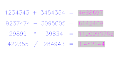
We extensively use FIELD object these days for several purposes like creating a custom plot stamp or printing the filename in the title block etc. When we dig in depth, FIELD object will provide us with a lot of possibilities. Here is a simple calculator application using the 'Formula' inside the 'Object' category of field.
We are going to develop the calculator as an attributed block reference where you can modify the attribute values to get the result in another attribute. For this purpose, create on block with attributes FIRST_NUMBER,OPERATOR,SECOND_NUMBER and RESULT attributes and insert it into the drawing.
Insert the block and edit attributes in the Edit Attributes dialog. Leave the first three attributes as we are not going to do any field operations over there. Right click on the last attribute (RESULT) and select 'Insert Field' option as shown in the picture.
We are going to develop the calculator as an attributed block reference where you can modify the attribute values to get the result in another attribute. For this purpose, create on block with attributes FIRST_NUMBER,OPERATOR,SECOND_NUMBER and RESULT attributes and insert it into the drawing.
Insert the block and edit attributes in the Edit Attributes dialog. Leave the first three attributes as we are not going to do any field operations over there. Right click on the last attribute (RESULT) and select 'Insert Field' option as shown in the picture.

You will be provided with field dialog box. Select 'Objects' field category and choose 'Formula' from the field names. Now right click on the 'Formula' text box and choose 'Insert Field' option once again (See the picture).

Now an additional field dialog will show up. This time select 'Object' field name from the 'Objects' category. Select the inserted block using the small button located near the 'Object type' text box. Once selected, the block properties including the attributes will be shown up in the properties list box. Select the FIRST_NUMBER attribute from the list and click 'Ok'.

Repeat the steps 3 and 4 to include the attributes OPERATOR and SECOND_NUMBER in the formula text box as shown in the picture. That's it. Press ok to finish the procedure.

Try changing the FIRST_NUMBER, OPERATOR and SECOND_NUMBER values. if the FIELDEVAL system variable is properly set, you will see the result soon after the next regen.

If you want to know how to create 'Live Fields' inside a drawing, see the AutoClock post.
Subscribe to:
Posts (Atom)


