Saturday, September 26, 2009

Extracting 3D DWF Model Properties Using Autodesk Design Review API and AutoCAD VBA

A while ago I came across a situation where I had to extract line lists, valve lists, equipment lists and fittings lists from a DWF file. The DWF file was converted from a PDS model review file (DRI) using NavisWorks. After a few hours research on Autodesk Design Review API, I could extract all the required lists with a few lines of code. Ofcourse, with the help of fast dying AutoCAD VBA.

As the code makes use of CExpressViewerContol, you need to place it inside a form before running the code. You may use any COM compliant development environment in place of AutoCAD VBA. But I would like to stick to AutoCAD VBA till its last breath due to ease of use.

Sub ExtractDwfProps()
'### Extracts properties from model components of a 3D DWF file
'### By zoomharis@gmail.com
'### Date: 09/09/09

'### Based on Autodesk Design Review 2010 API

'### DWF specific references
' -----------------------
'### AdCommon 1.0 Type Library
'### ECompositeViewer 1.0 Type Library
'### ExpressViewerDll 1.0 Type Library

'### DWF specific controls
' ---------------------
'### CExpressViewerContol

On Error Resume Next
Dim oECV As ECompositeViewer.IAdECompositeViewer
Dim oSec As ECompositeViewer.IAdSection
Dim oEnt As AdCommon.IAdObject
Dim oProp As AdCommon.IAdProperty
Dim oCol As AdCommon.CAdCollection
Dim oCont As ECompositeViewer.IAdContent
Dim strDwfLoc As String
Dim strPropName As String
Dim strPropValue As String
'## Let me use a sample 3D dwf file
strDwfLoc = "C:\Dwf\3DModel.dwf"
strPropName = ""
strPropValue = ""
'## Open the dwf file in the viewer
CExpressViewerContol1.SourcePath = strDwfLoc
Set oECV = CExpressViewerContol1.ECompositeViewer
'## Iterate through the dwf model
For Each oSec In oECV.Sections
Set oCont = oSec.Content
Set oCol = oCont.Objects(0)
For Each oEnt In oCol
For Each oProp In oEnt.Properties
strPropName = oProp.Name
strPropValue = oProp.value
Next
'## Write code here to apply conditions to filter the list
'## and send the extracted info into a text or excel file.
'## Then clear the property name and property value strings
strPropName = ""
strPropValue = ""
Next
Next
Set oProp = Nothing
Set oEnt = Nothing
Set oCol = Nothing
Set oCont = Nothing
Set oSec = Nothing
Set oECV = Nothing
End Sub

I have stripped down some of the code portion as it was specific my purpose. This is mostly in a general form and you may need to add/modify wherever necessary in order to run it in your system.

Saturday, September 12, 2009

Creating Complex Selection Sets Using FILTER Command

It always make me wonder why the FILTER command is often overlooked by most of the AutoCAD users of current era, especially the newbies. It may be partially due to the fact that this command can get highly complicated at times depending upon the requirement. Ofcourse, it can be. But the power is always accompanied by complexity. Some of the advantages of this most powerful selection tool are;
  • Creating selection sets based upon multiple criteria
  • Creating logical groups without physically grouping it
  • Flexibility to use transparently in between the commands

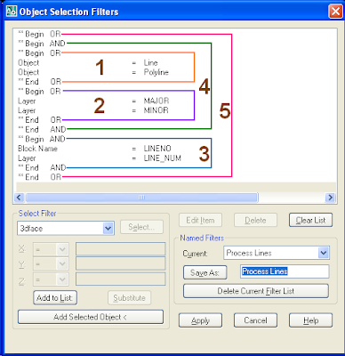
To make it simple (sorry, if you find it otherwise ;-), let us go by a sample. I have a Piping & Instrumentation diagram in which I need to create a selection set of major and minor process lines along with the line numbers. The newbie designer has drawn some of the lines as LINE entity and rest of them as POLYLINE entity. All the major lines are placed inside 'MAJOR' layer and the minor ones in 'MINOR' layer. The line number is placed inside an attributed block reference named 'LINENO' which resides in 'LINE_NUM' layer. The image below illustrates the filter criteria for creating the above selection set.


This is a nested filter criteria that makes it little difficult to understand. Nothing to worry. Let us split it into smaller portions so that we can analyse it easily.Following is the description of each portion in the order as shown in the image.


  1. Object= 'LINE' OR 'POLYLINE'
  2. Layer = 'MAJOR' OR 'MINOR'
  3. Block_Name = 'LINENO' AND Layer = 'LINE_NUM'
  4. Result of Step-1 AND Step-2
  5. Result of Step-3 AND Step-4.

If you represent the whole thing as a logical expression, it would look like the following statement;

((( Object= 'LINE' OR 'POLYLINE') AND (Layer = 'MAJOR' OR 'MINOR')) OR (Block_Name ='LINENO' AND Layer = 'LINE_NUM'))

If you have a closer look at the filter, you will find that the innermost criteria gets resolved first and passes its result to the outer ones in nested filters. In the above case, the criteria to be executed at the final stage is the outermost one (Step-5).

This way, you can save very complex filters in your drawing for quick access at any stage of drawing development or review.