Wednesday, November 19, 2008

Developing a Sine Wave Generator using DIECAL

In the last post, we saw how easiy we could accomplish complicated operations using DIECAL. Further to that, we are going develop a sine wave generator using a few lines of code. I know that you don't have a sine wave generator even in your wildest DIESEL dreams. But it is a really simple task using DIECAL. Once again, I am going to use points in order to make it simple. For generating sine wave, use the following macro.

*^C^C_setvar;userr1;$M=$(+,$(getvar,userr1),$(getvar,userr2))$(if,$(>=,$(*,$(+,$(getvar,userr1),$(getvar,userr2)),10),$(*,$(getvar,userr3),360)),^C)_Point;'CAL;[$(getvar,userr4)+$(+,$(getvar,userr1),$(getvar,userr2))/18,sin(10*$(+,$(getvar,userr1),$(getvar,userr2)))];

The above macro makes use of USERR1 to USERR4 system variables. The USERR1 and USERR2 values are automatically set by the set/reset macro (given below). USERR3 holds the value for number of cycles created and USERR4 is for X axis lag value (See the sample image). Use the following macro to set/reset initial values. When you run this macro, just follow the status bar messages.

^C^C_setvar;userr1;-1;;userr2;1;userr3;1;_modemacro;Enter number of cycles:;userr3;\userr4;0;_modemacro;Enter lag value for X axis:;setvar;userr4;\_modemacro;.;

The following image illustrates three sine waves gererated with a cycle value of 3 and X axis lag value 0 (Red) .22 (Green) and .44(Yellow).


Thursday, November 13, 2008

DIECAL - It's DIESEL Enhanced with a Mathematical Engine

In the last post I mentioned that I could come up with some better posts after the vacation, with the help of a refreshed mind. Hope this post justifies my words.

The absence of a strong mathematical engine inside DIESEL has troubled most of us in the past. We are going to overcome this limitation by mixing up DIESEL with the command line calculater. It should work in AutoCAD LT as command line calculator has been included in LT2009.If you compare, DIECAL capabilities are far better than DIESEL. Using DIECAL, you can do vector calculations, access various numeric functions which are not available in DIESEL and can do so many other things. If you are not convinced, here is a sample macro to draw a sphere by placing points across the surface of a sphere.

*^C^Csetvar;userr1;$M=$(+,$(getvar,userr1),$(getvar,userr4));$(if,$(>=,$(getvar,userr1),360),setvar;userr2;$
(+,$(getvar,userr2),$(getvar,userr5));setvar;userr1;0;)_Point;'CAL;[$(getvar,userr3)
<$(+,$(getvar,userr1),$(getvar,userr4))<$(getvar,userr2)];$(if,$(>,$(getvar,userr2),270),^c)


This macro uses USERR1 to USERR5 system variables to store values. The USERR1 and USERR2 system variable values are handled by the above macro. The USERR3 system variable stores the radius of the sphere, USERR4 holds the angle between the horizontal points and USERR5 holds the angle between vertical points. These values can be set/reset using the following macro. When you run this macro, just follow the instructions shown in the status bar.

^C^C_setvar;userr1;0;;userr2;90;_modemacro;Enter sphere radius:;userr3;\_modemacro;Enter angle between horizontal points:;userr4;\_modemacro;Enter angle between vertical points:;userr5;\_modemacro;.;

Please remember to run this macro to set/reset values before using the main macro.The first macro makes use of the Spherical Coordinate System point format entry to place points across the surface of the sphere.Please note that the CAL command has to be invoked transparently ('CAL) in the macro in order to output the result of calculation to the active command. It's my lack of knowledge in mathematics that prevents me from showing off a powerful application to exihibit the true potential of DIECAL. Those who know trigonometry and vector algebra will really enjoy this method. Following are some sample spheres made using different radius and angle values.


Point Sphere - 3D View


Point Sphere - Top View

Due to the presence of 3D elements, I am not quite sure whether the LT people can use the above macro. But they can surely develop a lot of advanced macros using DIECAL. To get an idea of things that can be done using DIECAL, refer to command line calculator section in AutoCAD help. Now even AutoCAD LT seems to be really unlimited. Doesn't it?

Thursday, October 16, 2008

A Shortcut for Jumping over Words in AutoCAD

This method works fine almost everywhere in windows; be it a word processor, text editor or a dialog prompt. But I thought it would be really interesting to the AutoCAD people who normally deal with a lot of text in day to day life.

You can use CTRL + Right Arrow key to move to the next word or CTRL + Left Arrow key to move to the previous word while you are editing text inside AutoCAD. It successfully worked wherever I tried including Edit Text dialog box, Edit Attributes dialog box, MText Editor and Enhanced Attribute Editor. You can also use CTRL + Up/Down arrows to move to the beginning and end of a MText paragraph.

Thanks to Digital Inspiration for the tip. By the way, I am going back home on vacation for the next three weeks and might not be spending time in front of the computers during the period. Hope to post some good stuff after the trip with the help of a 'refreshed mind' ;-)

Friday, October 10, 2008

Wake up Dubai / U.A.E CADers....Shaan Hurely is coming to meet you...!!

Shaan Hurely is currently Platform Technology Evangelist for the AutoCAD & Platform Products as well as author of one of the most popular AutoCAD blogs, Between the Lines . Don't miss this oppertunity to grab his wealth of experience, knowledge and wisdom. He is available in Dubai on 26th of October. His visiting purpose in his own words;

"I will be presenting about AutoCAD and its future development as well as other topics in Istanbul Turkey, Kuwait, and Dubai in the next two weeks. I want to invite all AutoCAD customers in the region to the events or to possibly arrange for a private meeting at your office to discuss your use of AutoCAD and the future of AutoCAD. All events and meetings are free. This is not a sales presentation but focused on product use and technical topics. I am extremely excited to visit customers in these locations and honored to have been invited."

Unfortunately I miss the oppertunity to catch him as I will be back in India for my vacation. You can see the program details in his blog.

Welcome Aboard Shaan....!!

Monday, October 6, 2008

Exploring AutoCAD Field Capabilities by Developing a Simple Field Calculator

We extensively use FIELD object these days for several purposes like creating a custom plot stamp or printing the filename in the title block etc. When we dig in depth, FIELD object will provide us with a lot of possibilities. Here is a simple calculator application using the 'Formula' inside the 'Object' category of field.

We are going to develop the calculator as an attributed block reference where you can modify the attribute values to get the result in another attribute. For this purpose, create on block with attributes FIRST_NUMBER,OPERATOR,SECOND_NUMBER and RESULT attributes and insert it into the drawing.

Insert the block and edit attributes in the Edit Attributes dialog. Leave the first three attributes as we are not going to do any field operations over there. Right click on the last attribute (RESULT) and select 'Insert Field' option as shown in the picture.


You will be provided with field dialog box. Select 'Objects' field category and choose 'Formula' from the field names. Now right click on the 'Formula' text box and choose 'Insert Field' option once again (See the picture).


Now an additional field dialog will show up. This time select 'Object' field name from the 'Objects' category. Select the inserted block using the small button located near the 'Object type' text box. Once selected, the block properties including the attributes will be shown up in the properties list box. Select the FIRST_NUMBER attribute from the list and click 'Ok'.


Repeat the steps 3 and 4 to include the attributes OPERATOR and SECOND_NUMBER in the formula text box as shown in the picture. That's it. Press ok to finish the procedure.


Try changing the FIRST_NUMBER, OPERATOR and SECOND_NUMBER values. if the FIELDEVAL system variable is properly set, you will see the result soon after the next regen.

If you want to know how to create 'Live Fields' inside a drawing, see the AutoClock post.

Tuesday, September 16, 2008

Lvl2Lyr - A Utility to Translate DGN levels to AutoCAD layers using AutoCAD VBA

Since Autodesk and Bentley have announced an agreement to expand interoperability between their applications, I thought it would be nice to have a look into the microstation API through AutoCAD VBA. I learnt a thing or two about Microstation VBA by doing the following utility. This programs imports Level structure from a DGN file to the current drawing converting it to an equivalent layer structure. For this program to work properly, you need to include reference to 'Bentley Microstation DGN 8.0 Object Library' inside VBA IDE. The utility was tested using AutoCAD 2008 and Microstation V8.


Sub Lvl2Lyr()
'## Translates Microstation levels to AutoCAD Layers
'## Based on AutoCAD 2008 and Microstation V8.0
'## Include reference to 'Bentley Microstation DGN 8.0 Object Library'
'## By Mohamed Haris (zoomharis@gmail.com)
'## ------------------------------------------------------------------
On Error Resume Next
Dim oMS As New MicroStationDGN.Application
Dim oMSdf As DesignFile
Dim oMSlvls As Levels
Dim oMSlvl As Level
Dim oMSct As ColorTable
Dim lngMScol As Long
Dim oCol As New AcadAcCmColor
Dim sLType As String
Dim oLyr As AcadLayer
Dim red As Byte, green As Byte, blue As Byte
Dim eDwgLWs As Variant
ThisDrawing.Utility.Prompt vbCrLf & _
"Importing layer settings from Microstation....."
'## C:\Test.dgn is the sample file used
Set oMSdf = oMS.OpenDesignFile("C:\Test.dgn")
'## Get the color table from the DGN file
Set oMSct = oMSdf.ExtractColorTable
Set oMSlvls = oMSdf.Levels
'## Iterate through each level to grab the properties
For Each oMSlvl In oMSlvls
'## Prefix MS_ with each layer name to make out the imported layers
Set oLyr = ThisDrawing.Layers.Add("MS_" & oMSlvl.Name)
'## Remove the brackets from the linetype name before used in Acad
sLType = Trim(Replace(Replace(oMSlvl.ElementLineStyle.Name, _
"(", "", , , vbTextCompare), ")", "", , , vbTextCompare))
'## Hope the linetypes are available in Acad
ThisDrawing.Linetypes.Load sLType, "acad.lin"
'## Set linetype for the layer
oLyr.Linetype = sLType
'## Don't know a better way to convert DGN colors to DWG colors
'## Grabbed RGB from DGN and applied it in the DWG
lngMScol = oMSct.GetColorAtIndex(oMSlvl.ElementColor)
red = lngMScol Mod &H100
lngMScol = lngMScol \ &H100
green = lngMScol Mod &H100
lngMScol = lngMScol \ &H100
blue = lngMScol Mod &H100
oCol.SetRGB red, green, blue
'## Set layer color
oLyr.TrueColor = oCol
'## Is layer isolated?
oLyr.LayerOn = oMSlvl.IsDisplayed
'## Is layer frozen?
oLyr.Freeze = oMSlvl.IsFrozen
'## Is layer locked?
oLyr.Lock = oMSlvl.IsLocked
'## Is layer Plottable?
oLyr.Plottable = oMSlvl.Plot
'## Layer description
oLyr.Description = oMSlvl.Description
'## Convert lineweights
'## Define a enum array with respect to DGN lineweights from 0 to 31
eDwgLWs = Array(acLnWt000, acLnWt013, acLnWt030, acLnWt040, acLnWt053, _
acLnWt070, acLnWt080, acLnWt100, acLnWt106, acLnWt120, _
acLnWt140, acLnWt158, acLnWt158, acLnWt158, acLnWt200, _
acLnWt211, acLnWt211, acLnWt211, acLnWt211, acLnWt211, _
acLnWt211, acLnWt211)
oLyr.Lineweight = eDwgLWs(oMSlvl.ElementLineWeight)
Next
'## Close the DGN file
oMSdf.Close
'## Quit Microstation application
oMS.Quit
ThisDrawing.Utility.Prompt vbCrLf & "Layer settings were imported from Microstation." & vbCrLf
Set oCol = Nothing
Set oLyr = Nothing
Set oMSlvl = Nothing
Set oMSlvls = Nothing
Set oMSct = Nothing
Set oMSdf = Nothing
Set oMS = Nothing
End Sub

Tuesday, September 9, 2008

Advanced Drag & Drop Operations - Link to a Specific Excel Cell or Range

Have you ever tried linking an AutoCAD object to a specific cell or row? For example, you might want to link a door block with a specific row inside the door schedule. Follow the easy steps to accomplish the task.

  • Keep the Excel file and the drawing open.

  • Select the required cell by clicking on it.

  • Move the cursor towards the side of the cell until you see the move symbol (Similar to what you see inside the lens in zoom extents button icon).

  • Now right click and drag the cell to the AutoCAD window.

  • On releasing the right mouse button, you will be provided with a menu containing a menu item 'Create hyperlink here' as shown below.


  • Select the AutoCAD entity to be linked when prompted for object selection.

  • Close the excel file and click on the AutoCAD entity holding down the Ctrl key to check the link.
You can modify the above link to select a range of cells instead of a single cell.Press Ctrl+K and select the previous AutoCAD entity to open 'Edit Hyperlink' dialog box. At the end of the link, you will see something like file name.xls#sheet name!cell number. For example, suppose you are linking the C3 cell of Sheet1 of Test.xls placed in C: drive, then the link path will be C:\Test.xls#Sheet1!C3. In order to link a range of cells, you have to modify the above syntax to file name.xls#sheet name!cell number1:cell number2. ie, in the above example, it will become C:\Test.xls#Sheet1!C3:E6 to link a range of C3:E6.

Try to link a word paragraph using the above method and let me know how you achieved the desired result.

Advanced Drag & Drop Operations - Load / Run Scripts / LISP / VBA / ARX

Depending upon the type of files, there may be slight variations in the drag & drop result. Let's see how each file type responds.

Script: If you drag and drop a script file into the autocad window, it executes the script.

LISP: If you drag and drop a file containing LISP expressions but not a function definition, it straight away executes the LISP expressions. If the file consists of any LISP function definitions, it loads the functions into AutoCAD.

VBA: If you drag and drop a DVB file, it loads that project. The VBA module files (BAS extension) doesn't support drag and drop loading.

ARX: Loads the specific ARX application.

You can also use the drag and drop method to load other customization files like CUI, MNS etc.

Thursday, September 4, 2008

Advanced Drag & Drop Operations - Insert & Link Raster Images

Do you know the easiest way to attach an image? It's a simple drag (left click) and drop from windows explorer to AutoCAD drawing. Let's see how to link a an external image to an attached image. For example, you might want to link an overall plot plan image to a plot plan . For that, right click and drag the destination image to the drawing. When you drop it there, you will find a menu with 'Create hyperlink here' as shown below.

Click on that and select the attached image when prompted for selection. To test the link, hold down the Ctrl key and click on the image.

Advanced Drag & Drop Operations - Copy Text from a Web Page / MS Outlook / Text File

This time we will see how to copy text from a web page, Outlook and a text file.

To copy text from a text file
To copy text from a text file, left click the text file from explorer window, then drag and drop it to the host drawing.

To copy text from web page or outlook
Open the web page or email, then highlight required portion of text then drag and drop it into AutoCAD window.

In both the cases, it will be copied as MText.

Advanced Drag & Drop Operations - Attach a Drawing as an External Reference

As a continuation of previously posted drag & drop operations (Move Text Inside Edit Text Dialog and Move Text Inside Edit Attributes Dialog), we are going to look into some more intersting ones. You already know that dragging a DWG file into empty AutoCAD application window opens that file over there and in case any drawings are already open there,it inserts the dragged drawing as a block. Apart from this, if you need to attach the drawing file as an external reference, follow the steps given below.


  • Locate the drawing file to be attached inside explorer window.

  • Right click and drag the file into the host drawing already opened in AutoCAD.

  • When you leave the right mouse button, you will see a menu as shown below. Choose 'Create Xref' from the menu.


That's it. Now you have the dragged drawing attached as an external reference. We will see more drag & drop operations in the next posts.


Wednesday, August 27, 2008

AutoClock - An AutoCAD Digital cum Analog Clock Using AutoCAD Script and DIESEL

Here is an AutoCAD digital cum (partially) analog clock developed using a combination of AutoCAD Script and DIESEL. It shows current time in digital format updated as in a normal digital clock plus date and month along with a rotating seconds needle. I hope this program will help us to learn how to combine DIESEL and script effectively to acheive powerful results. The macro and script are pretty simple as illustrated below.

^C^C_Setvar;fielddisplay;0;_Undo;;;control;none;
_Select;\_Change;previous;;0,0;0;
_Rotate;previous;;0,0;$M=$(-,0,$(*,$(edtime,$(getvar,date),SS),6));
_Script;AutoClock.scr

Let us have a look at the macro in detail.

  1. _Setvar;fielddisplay;0;
    Sets field display for the digital elements.

  2. _Undo;;;control;none;
    Disables Undo action. If the Undo is on, it will consume a lot of memory in a long run resulting in application instability.

  3. _Select;\_Change;previous;;0,0;0;
    Resets the seconds needle to the default position (towards 12).

  4. _Rotate;previous;;0,0;$M=$(-,0,$(*,$(edtime,$(getvar,date),SS),6));
    Moves the seconds needle to the current seconds position.

  5. _Script;AutoClock.scr
    Runs the script to update the clock at an interal of 1 second.

Arrange the above macro in a button and place the following script inside a text file named 'AutoClock.scr' and keep it somewhere inside the AutoCAD search path (for example, inside AutoCAD support directory).

_Rotate
previous

0,0
-6
delay 1000
Regen
rscript


If you want to try AutoClock, then download the required files and follow the instructions inside the readme file. To activate the clock, run the above macro and select the seconds needle when select objects prompt is displayed. The seconds needle accuracy may vary depending upon the command execution time. You can fine tune the clock accuracy by adjusting the delay. A delay just above 900 in place of 1000 works fine for me.

Join the AUGI group at Autodesk University

Those who wish to join AUGI at AU, please use the following links. I wish if I could join, but my chances of participating the AU are very less :-(.

Join the “AUGIatAU” Online Group
AUGIatAU Online Group

Follow AUGIatAU on twitter

Thanks to Mike Perry, the ever hardworking AUGI Forums Director for the above information. For those who don't know, Mike Perry himself has made over 14,000 posts in the AUGI Forums. Quite unbelievable figure, isn't it?

[UPDATE]
Oops... I typed AutoCAD university in place of Autodesk university in the title. Am I thinking too much about AutoCAD? ;-)
[END UPDATE]

Wednesday, August 20, 2008

A Special Break Utility for AutoCAD LT People Using DIESEL

This is an attempt to mimic the AutoLISP/VBA functionality in AutoCAD LT using DIESEL.This macro prompts the user for an intersection point and breaks the intersecting objects like Line, Polyline, Arc, SPline equally from either sides. The break gap can be adjusted using the USERR1 system variable. If you don't provide any value to the USERR1 system variable, it cuts the line at the intersection point without leaving any gap in between. Before having a look at the macro, let me remind you that the macro has not been tested in AutoCAD LT (as usual) because there is no AutoCAD LT with me because there is no need to use AutoCAD LT because there is Vanilla AutoCAD with me. Here goes the macro.

*^C^C_setvar;osmode;0;ucs;object;int;\Break;$M=$(getvar,lastpoint);F;
@$(getvar,userr1)<0;@$(*,2,$(-,0,$(getvar,userr1)))<0;ucs;previous;


Let us have a close look at the macro functionality.

  1. _setvar;osmode;0;
    Disables the running object snap

  2. ucs;object;int;\
    Picks an object at an intersection point. The picked point will be stored in the LASTPOINT system variable. Also the UCS will be arranged according to the object so that we can provide the angle 0 for all objects with different angles.

  3. Break;$M=$(getvar,lastpoint);F;@$(getvar,userr1)<0; @$(*,2,$(-,0,$(getvar,userr1)))<0;
    At the select object prompt of the break command, we provide the LASTPOINT system variable stored previously. We select the first break point relative to the last picked point (i.e. intersection point) at 0 angle (because the UCS has already been aligned with the object). The second break point is calculated relative to the first break point. The formula used is SBP=(0-FBP)*2 where FPB is the first break point and SBP is second break point. For example, if the value of USERR1 is set to 2 then the first point will be specified as @2<0 and the second point will be @-4<0.

  4. ucs;previous;
    Resets the UCS to previous one.

Since we are picking only the intersection point, it is quite unpredictable that which one of the two mutually intersecting entities will get trimmed. One way to overcome this problem is to change the draw order of the entities.For example, suppose you have got a few horizontal as well as vertical intersecting lines. To break the horizontal lines, select all horizontal lines, then go to Tools Menu (or right click) then go to Draw Order and choose 'Bring to Front'. Otherwise the entities will get trimmed according to their draw order. In the following picture, blue lines were placed above the red lines and red lines were placed above the magenta lines.


I hope the LT people will find this macro very helpful. If somebody tries this macro in LT, let us know the result.

Wednesday, August 13, 2008

An Automated Guiding System for Newcomers Using AutoCAD VBA and Microsoft Speech

Have you found the title a little bit confusing? Let me elaborate it. What we are going to see is a simple event oriented AutoCAD VBA program to guide newcomers in a company through proper way until they get familiar with Dos and Don'ts as well as company standards. The program given below is pretty simple and is only intented to show how the system can be implemented. It requires Microsoft Speech (Text-to-speech) to be available in your system. If you wish to implement a comprehensive system, you would better write your code in class modules. Again, this system is not recommended for experienced users as it will definitely check their patience. Here goes the code.

Private Sub AcadDocument_BeginCommand(ByVal CommandName As String)

On Error Resume Next

Dim objSSV As Object

Set objSSV = CreateObject("Sapi.SpVoice")

With objSSV

Select Case CommandName

Case "SAVEAS", "QSAVE", "SAVE"

.speak "Please make sure that the saved drawing version is as per client standard"

Case "BLOCK", "WBLOCK"

.speak "All blocks shall be made in zero layer"

Case "LAYER"

.speak "Please refer CAD manual for standard layering system"

Case "EXPLODE"

.speak "No standard blocks shall be exploded for editing"

Case "REFEDIT", "BEDIT"

.speak "Please contact CAD support before editing any standard blocks"

End Select

End With

Set objSSV = Nothing

End Sub

Keep the above code inside the 'ThisDrawing' section of Visual Basic Editor (for testing purpose) and turn the speakers on. Run any of the fore-mentioned commands inside AutoCAD. You will hear instructions based on the commands. Hope this system will help senior guys to avoid running behind the newcomers for correction and teaching purposes.

Sunday, August 10, 2008

A Fancy Line Command Using DIESEL

This is just meant for fun. Infact, there is nothing much fancy inside the command as the title indicates. All that does is drawing continuous line segments with diffrent colours. Let's have a look at the macro.

*^c^c$M=$(if,$(eq,$(getvar,modemacro),""),_id;\setvar;modemacro;Fancy Line Command - reset the sysvars USERI1 and MODEMACRO before next use;)$(if,$(and,$(<,$(getvar,useri1),255),$(!=,$(getvar,useri1),0)),setvar;useri1;$(+,$(getvar,useri1),1);_-color;$(getvar,useri1);_Line;$(getvar,lastpoint);\,setvar;useri1;1)


The program flow is as described below.

  • First check whether the modemacro system variable is empty - $(eq,$(getvar,modemacro),"").

  • If it's empty then prompt for a starting point for the line and set the mode macro system variable - _id;\setvar;modemacro;Fancy Line Command - reset the sysvars USERI1 and MODEMACRO before next use;

  • If it is not empty, then the first point has already been selected, now we have to check for the ACI color index limits stored inside the useri1 system variable - $(and,$(<,$(getvar,useri1),255),$(!=,$(getvar,useri1),0))
  • If everything is ok, then increment the color index value by 1, set the color value and draw a line with that color - setvar;useri1;$(+,$(getvar,useri1),1);_-color;$(getvar,useri1);_Line;$(getvar,lastpoint);\

  • If the color index is not within the ACI limits, then skip the previous step and set the color index value inside useri1 to 1 (Red color) - setvar;useri1;1

  • Continue the above steps until the user press escape button - *^c^c
You will have to reset the system variables before using the command next time (Though, I don't see anybody using it for the second time ;-) . Here goes the reset macro.

^c^c_setvar;modemacro;.;;useri1;0

Shown below is an output image of the command.


Tuesday, August 5, 2008

Quick Tip - A better way to handle heavy raster images

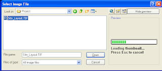
Isn't it really painful to work with huge raster images? Those who have worked previously know how irritating it can be. But you can reduce the pain to a certain extent by using some of the availabe options. Switching off the image preview is one of them.


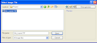
As you can see, it takes time to generate the thumbnail preview of the image. The bigger the image size, the longer it takes to generate the preview. You can switch off the preview by clicking on the 'Hide Preview' button on top right corner of the dialog box. Once you have switched it off, the button caption will change to 'Show Preview'. When you finish processing the big files, you can turn the preview on by clicking on it.


I often work with large tiff images and this feature saves a lot of time for me.

Saturday, July 19, 2008

A Shortcut for Plotting with Previous Page Setup

Hi everybody,
I have been away from blogosphere for a short while (a period of almost 9 months ...!!). I don't know how I could stay away from the CADD world for such a long time. It was really painful not getting updated with the latest CADD info, but at the same time had a very sweet and memorable time spent with my family back home. Now feel pretty happy to be back in the role of a CAD Admin, a job I had been longing for a long time.

Two weeks ago, one of my friends emailed me seeking an easier way to plot with previous page setup without opening the plot dialog. I was lucky to have successfully tried the following macro in AutoCAD 2005 and AutoCAD 2008 versions.

^C^C-Plot;No;;Previous Plot;;No;No;Yes

The most important aspect of this macro is to provide 'Previous Plot' at the page setup name prompt. Keep the macro inside a button or menu. Or else, you can easily convert this macro to create a lisp routine and assign a shortcut for that as shown below.

(defun c:PP()(Command "-Plot" "No" "" "Previous Plot" "" "No" "No" "Yes"))