Have you had the habit of working on isometric drawings frequently? I do a lot of isometric drawings during my work. While doing these drawings, you may need to switch between rectangular and isometric snaps several times. Here is a simple macro to easily switch between these snap modes.
^C^C_setvar;SNAPSTYL;$M=$(if,$(=,$(getvar,SNAPSTYL),0),1,0)
I found a similar macro commented by Kate Morrical in her own blog LT Unlimited. Here goes Kate's version.
$M=$(if,$(=,$(getvar,SNAPSTYL),1),SNAPSTYL;0;;,SNAPSTYL;1;;)
Thanks Kate, for the handy macro.
Showing posts with label DIESEL. Show all posts
Showing posts with label DIESEL. Show all posts
Monday, March 21, 2011
Thursday, July 8, 2010
A Macro for Aligning Text, MText and Block Entities Horizontally and Vertically in AutoCAD LT
It has been a long time since I made my last post here. I was seriously thinking of dropping the blogging activities, mainly due to lack of unique ideas. But when I received an email request from a AutoCAD LT user for a macro for aligning objects like Text entities, I couldn't resist trying it out and sharing it with you people. My sincere apologies to all readers for leaving such a long gap. That said, to be honest, I don’t have any idea when I am going to publish my next tip over here.
Back to our post topic. These macros can be used to align entities like Text, Mtext, Blocks and literally any object that comes with an insertion base point, both horizontally and vertically.That means you can use this macro to align a Text entity with an MText or Block Reference. The only limitation you will come across is that you will have to select the entities one by one as opposed to selecting all together in AutoLISP or VBA programs.
You have already seen the power of combining DIESEL with the CAL command (I call it DIECAL for ease of use). Once again, I am going to use the power of DIECAL to accomplish our task. Here goes the first macro, used for aligning entities vertically.
*^C^C$M=$(if,$(=,$(getvar,useri5),0),osmode;0;_id;\userr3;'cal;rxof(@);\)useri5;0;select;single;\lastpoint;'cal;ins;@;\userr4;'cal;ryof(@);\userr5;'cal;rzof(@);\useri5;1;_move;p;;'cal;@;'cal;xof([getvar(userr3),0,0])+yof([0,getvar(userr4),0])+zof([0,0,getvar(userr5)]);
For you to get an idea how it works, please find the image below consisting of different types of entities.

The next picture illustrates what the align vertical macro can do with these entities.

With a small modification in the macro, you can use it to align these entities horizontally as well. Here is the modified macro for horizontal alignment.
*^C^C$M=$(if,$(=,$(getvar,useri5),0),osmode;0;_id;\userr4;'cal;ryof(@);\)useri5;0;select;single;\lastpoint;'cal;ins;@;\userr3;'cal;rxof(@);\userr5;'cal;rzof(@);\useri5;1;_move;p;;'cal;@;'cal;xof([getvar(userr3),0,0])+yof([0,getvar(userr4),0])+zof([0,0,getvar(userr5)]);
And here is the illustration of the macro functionality.
Before running the macro.

After running the macro.

These macros have been tested in AutCAD LT 2011 and works fine over there. I hope it will work with previous versions also, at least in the recent versions of AutoCAD LT. If you come across any problems, please feel free to post it here.
Many thanks to Adam for inspiring me to develop this :-)
Wednesday, November 19, 2008
Developing a Sine Wave Generator using DIECAL
In the last post, we saw how easiy we could accomplish complicated operations using DIECAL. Further to that, we are going develop a sine wave generator using a few lines of code. I know that you don't have a sine wave generator even in your wildest DIESEL dreams. But it is a really simple task using DIECAL. Once again, I am going to use points in order to make it simple. For generating sine wave, use the following macro.
*^C^C_setvar;userr1;$M=$(+,$(getvar,userr1),$(getvar,userr2))$(if,$(>=,$(*,$(+,$(getvar,userr1),$(getvar,userr2)),10),$(*,$(getvar,userr3),360)),^C)_Point;'CAL;[$(getvar,userr4)+$(+,$(getvar,userr1),$(getvar,userr2))/18,sin(10*$(+,$(getvar,userr1),$(getvar,userr2)))];
The above macro makes use of USERR1 to USERR4 system variables. The USERR1 and USERR2 values are automatically set by the set/reset macro (given below). USERR3 holds the value for number of cycles created and USERR4 is for X axis lag value (See the sample image). Use the following macro to set/reset initial values. When you run this macro, just follow the status bar messages.
^C^C_setvar;userr1;-1;;userr2;1;userr3;1;_modemacro;Enter number of cycles:;userr3;\userr4;0;_modemacro;Enter lag value for X axis:;setvar;userr4;\_modemacro;.;
The following image illustrates three sine waves gererated with a cycle value of 3 and X axis lag value 0 (Red) .22 (Green) and .44(Yellow).

Thursday, November 13, 2008
DIECAL - It's DIESEL Enhanced with a Mathematical Engine
In the last post I mentioned that I could come up with some better posts after the vacation, with the help of a refreshed mind. Hope this post justifies my words.
The absence of a strong mathematical engine inside DIESEL has troubled most of us in the past. We are going to overcome this limitation by mixing up DIESEL with the command line calculater. It should work in AutoCAD LT as command line calculator has been included in LT2009.If you compare, DIECAL capabilities are far better than DIESEL. Using DIECAL, you can do vector calculations, access various numeric functions which are not available in DIESEL and can do so many other things. If you are not convinced, here is a sample macro to draw a sphere by placing points across the surface of a sphere.
*^C^Csetvar;userr1;$M=$(+,$(getvar,userr1),$(getvar,userr4));$(if,$(>=,$(getvar,userr1),360),setvar;userr2;$
(+,$(getvar,userr2),$(getvar,userr5));setvar;userr1;0;)_Point;'CAL;[$(getvar,userr3)
<$(+,$(getvar,userr1),$(getvar,userr4))<$(getvar,userr2)];$(if,$(>,$(getvar,userr2),270),^c)
This macro uses USERR1 to USERR5 system variables to store values. The USERR1 and USERR2 system variable values are handled by the above macro. The USERR3 system variable stores the radius of the sphere, USERR4 holds the angle between the horizontal points and USERR5 holds the angle between vertical points. These values can be set/reset using the following macro. When you run this macro, just follow the instructions shown in the status bar.
^C^C_setvar;userr1;0;;userr2;90;_modemacro;Enter sphere radius:;userr3;\_modemacro;Enter angle between horizontal points:;userr4;\_modemacro;Enter angle between vertical points:;userr5;\_modemacro;.;
Please remember to run this macro to set/reset values before using the main macro.The first macro makes use of the Spherical Coordinate System point format entry to place points across the surface of the sphere.Please note that the CAL command has to be invoked transparently ('CAL) in the macro in order to output the result of calculation to the active command. It's my lack of knowledge in mathematics that prevents me from showing off a powerful application to exihibit the true potential of DIECAL. Those who know trigonometry and vector algebra will really enjoy this method. Following are some sample spheres made using different radius and angle values.

Point Sphere - Top View
The absence of a strong mathematical engine inside DIESEL has troubled most of us in the past. We are going to overcome this limitation by mixing up DIESEL with the command line calculater. It should work in AutoCAD LT as command line calculator has been included in LT2009.If you compare, DIECAL capabilities are far better than DIESEL. Using DIECAL, you can do vector calculations, access various numeric functions which are not available in DIESEL and can do so many other things. If you are not convinced, here is a sample macro to draw a sphere by placing points across the surface of a sphere.
*^C^Csetvar;userr1;$M=$(+,$(getvar,userr1),$(getvar,userr4));$(if,$(>=,$(getvar,userr1),360),setvar;userr2;$
(+,$(getvar,userr2),$(getvar,userr5));setvar;userr1;0;)_Point;'CAL;[$(getvar,userr3)
<$(+,$(getvar,userr1),$(getvar,userr4))<$(getvar,userr2)];$(if,$(>,$(getvar,userr2),270),^c)
This macro uses USERR1 to USERR5 system variables to store values. The USERR1 and USERR2 system variable values are handled by the above macro. The USERR3 system variable stores the radius of the sphere, USERR4 holds the angle between the horizontal points and USERR5 holds the angle between vertical points. These values can be set/reset using the following macro. When you run this macro, just follow the instructions shown in the status bar.
^C^C_setvar;userr1;0;;userr2;90;_modemacro;Enter sphere radius:;userr3;\_modemacro;Enter angle between horizontal points:;userr4;\_modemacro;Enter angle between vertical points:;userr5;\_modemacro;.;
Please remember to run this macro to set/reset values before using the main macro.The first macro makes use of the Spherical Coordinate System point format entry to place points across the surface of the sphere.Please note that the CAL command has to be invoked transparently ('CAL) in the macro in order to output the result of calculation to the active command. It's my lack of knowledge in mathematics that prevents me from showing off a powerful application to exihibit the true potential of DIECAL. Those who know trigonometry and vector algebra will really enjoy this method. Following are some sample spheres made using different radius and angle values.
 Point Sphere - 3D View

Point Sphere - Top View
Due to the presence of 3D elements, I am not quite sure whether the LT people can use the above macro. But they can surely develop a lot of advanced macros using DIECAL. To get an idea of things that can be done using DIECAL, refer to command line calculator section in AutoCAD help. Now even AutoCAD LT seems to be really unlimited. Doesn't it?
Wednesday, August 27, 2008
AutoClock - An AutoCAD Digital cum Analog Clock Using AutoCAD Script and DIESEL
Here is an AutoCAD digital cum (partially) analog clock developed using a combination of AutoCAD Script and DIESEL. It shows current time in digital format updated as in a normal digital clock plus date and month along with a rotating seconds needle. I hope this program will help us to learn how to combine DIESEL and script effectively to acheive powerful results. The macro and script are pretty simple as illustrated below.
^C^C_Setvar;fielddisplay;0;_Undo;;;control;none;
_Select;\_Change;previous;;0,0;0;
_Rotate;previous;;0,0;$M=$(-,0,$(*,$(edtime,$(getvar,date),SS),6));
_Script;AutoClock.scr
Let us have a look at the macro in detail.
- _Setvar;fielddisplay;0;
Sets field display for the digital elements. - _Undo;;;control;none;
Disables Undo action. If the Undo is on, it will consume a lot of memory in a long run resulting in application instability. - _Select;\_Change;previous;;0,0;0;
Resets the seconds needle to the default position (towards 12). - _Rotate;previous;;0,0;$M=$(-,0,$(*,$(edtime,$(getvar,date),SS),6));
Moves the seconds needle to the current seconds position. - _Script;AutoClock.scr
Runs the script to update the clock at an interal of 1 second.
Arrange the above macro in a button and place the following script inside a text file named 'AutoClock.scr' and keep it somewhere inside the AutoCAD search path (for example, inside AutoCAD support directory).
_Rotate
previous
0,0
-6
delay 1000
Regen
rscript
If you want to try AutoClock, then download the required files and follow the instructions inside the readme file. To activate the clock, run the above macro and select the seconds needle when select objects prompt is displayed. The seconds needle accuracy may vary depending upon the command execution time. You can fine tune the clock accuracy by adjusting the delay. A delay just above 900 in place of 1000 works fine for me.
Wednesday, August 20, 2008
A Special Break Utility for AutoCAD LT People Using DIESEL
This is an attempt to mimic the AutoLISP/VBA functionality in AutoCAD LT using DIESEL.This macro prompts the user for an intersection point and breaks the intersecting objects like Line, Polyline, Arc, SPline equally from either sides. The break gap can be adjusted using the USERR1 system variable. If you don't provide any value to the USERR1 system variable, it cuts the line at the intersection point without leaving any gap in between. Before having a look at the macro, let me remind you that the macro has not been tested in AutoCAD LT (as usual) because there is no AutoCAD LT with me because there is no need to use AutoCAD LT because there is Vanilla AutoCAD with me. Here goes the macro.
*^C^C_setvar;osmode;0;ucs;object;int;\Break;$M=$(getvar,lastpoint);F;
@$(getvar,userr1)<0;@$(*,2,$(-,0,$(getvar,userr1)))<0;ucs;previous;
Let us have a close look at the macro functionality.
I hope the LT people will find this macro very helpful. If somebody tries this macro in LT, let us know the result.
*^C^C_setvar;osmode;0;ucs;object;int;\Break;$M=$(getvar,lastpoint);F;
@$(getvar,userr1)<0;@$(*,2,$(-,0,$(getvar,userr1)))<0;ucs;previous;
Let us have a close look at the macro functionality.
- _setvar;osmode;0;
Disables the running object snap - ucs;object;int;\
Picks an object at an intersection point. The picked point will be stored in the LASTPOINT system variable. Also the UCS will be arranged according to the object so that we can provide the angle 0 for all objects with different angles. - Break;$M=$(getvar,lastpoint);F;@$(getvar,userr1)<0; @$(*,2,$(-,0,$(getvar,userr1)))<0;
At the select object prompt of the break command, we provide the LASTPOINT system variable stored previously. We select the first break point relative to the last picked point (i.e. intersection point) at 0 angle (because the UCS has already been aligned with the object). The second break point is calculated relative to the first break point. The formula used is SBP=(0-FBP)*2 where FPB is the first break point and SBP is second break point. For example, if the value of USERR1 is set to 2 then the first point will be specified as @2<0 and the second point will be @-4<0.
- ucs;previous;
Resets the UCS to previous one.
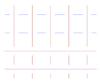
Since we are picking only the intersection point, it is quite unpredictable that which one of the two mutually intersecting entities will get trimmed. One way to overcome this problem is to change the draw order of the entities.For example, suppose you have got a few horizontal as well as vertical intersecting lines. To break the horizontal lines, select all horizontal lines, then go to Tools Menu (or right click) then go to Draw Order and choose 'Bring to Front'. Otherwise the entities will get trimmed according to their draw order. In the following picture, blue lines were placed above the red lines and red lines were placed above the magenta lines.

I hope the LT people will find this macro very helpful. If somebody tries this macro in LT, let us know the result.
Sunday, August 10, 2008
A Fancy Line Command Using DIESEL
This is just meant for fun. Infact, there is nothing much fancy inside the command as the title indicates. All that does is drawing continuous line segments with diffrent colours. Let's have a look at the macro.
*^c^c$M=$(if,$(eq,$(getvar,modemacro),""),_id;\setvar;modemacro;Fancy Line Command - reset the sysvars USERI1 and MODEMACRO before next use;)$(if,$(and,$(<,$(getvar,useri1),255),$(!=,$(getvar,useri1),0)),setvar;useri1;$(+,$(getvar,useri1),1);_-color;$(getvar,useri1);_Line;$(getvar,lastpoint);\,setvar;useri1;1)
The program flow is as described below.
^c^c_setvar;modemacro;.;;useri1;0
Shown below is an output image of the command.

*^c^c$M=$(if,$(eq,$(getvar,modemacro),""),_id;\setvar;modemacro;Fancy Line Command - reset the sysvars USERI1 and MODEMACRO before next use;)$(if,$(and,$(<,$(getvar,useri1),255),$(!=,$(getvar,useri1),0)),setvar;useri1;$(+,$(getvar,useri1),1);_-color;$(getvar,useri1);_Line;$(getvar,lastpoint);\,setvar;useri1;1)
The program flow is as described below.
- First check whether the modemacro system variable is empty - $(eq,$(getvar,modemacro),"").
- If it's empty then prompt for a starting point for the line and set the mode macro system variable - _id;\setvar;modemacro;Fancy Line Command - reset the sysvars USERI1 and MODEMACRO before next use;
- If it is not empty, then the first point has already been selected, now we have to check for the ACI color index limits stored inside the useri1 system variable - $(and,$(<,$(getvar,useri1),255),$(!=,$(getvar,useri1),0))
- If everything is ok, then increment the color index value by 1, set the color value and draw a line with that color - setvar;useri1;$(+,$(getvar,useri1),1);_-color;$(getvar,useri1);_Line;$(getvar,lastpoint);\
- If the color index is not within the ACI limits, then skip the previous step and set the color index value inside useri1 to 1 (Red color) - setvar;useri1;1
- Continue the above steps until the user press escape button - *^c^c
^c^c_setvar;modemacro;.;;useri1;0
Shown below is an output image of the command.

Saturday, July 19, 2008
A Shortcut for Plotting with Previous Page Setup
Hi everybody,
I have been away from blogosphere for a short while (a period of almost 9 months ...!!). I don't know how I could stay away from the CADD world for such a long time. It was really painful not getting updated with the latest CADD info, but at the same time had a very sweet and memorable time spent with my family back home. Now feel pretty happy to be back in the role of a CAD Admin, a job I had been longing for a long time.
Two weeks ago, one of my friends emailed me seeking an easier way to plot with previous page setup without opening the plot dialog. I was lucky to have successfully tried the following macro in AutoCAD 2005 and AutoCAD 2008 versions.
^C^C-Plot;No;;Previous Plot;;No;No;Yes
The most important aspect of this macro is to provide 'Previous Plot' at the page setup name prompt. Keep the macro inside a button or menu. Or else, you can easily convert this macro to create a lisp routine and assign a shortcut for that as shown below.
(defun c:PP()(Command "-Plot" "No" "" "Previous Plot" "" "No" "No" "Yes"))
Wednesday, September 26, 2007
Perform Loop Operations in AutoCAD LT using DIESEL
It's well known fact that you can not perform loop operations using DIESEL as you do in AutoLISP or other powerful programming languages. Isn't it really frustrating to have given up so many interesting tasks due to the absence of loop structures inside DIESEL? Let's give a try to stretch the LT limits a little bit and see how to mimic the loop operations using DIESEL.
The following macro illustrates how to use DIESEL to perfrom a loop operation. This macro calculates the factorial of a given number by iterating a required number of times. You can use the same logic to create various loop structures as per your requirement.
*^C^C$M=$(if,$(<=,$(getvar,USERI2),$(getvar,USERI1)),setvar;USERI3;$M=$(if,$(=,$(getvar,USERI2),1),1,$(*,$(getvar,USERI2),$(getvar,USERI3)));setvar;USERI2;$(+,$(getvar,USERI2),1),_modemacro;"The factorial of "$(getvar,USERI1)" is "$(getvar,USERI3);^C)
Before using the above macro, you need to run a simple macro to set up the user variables and the status bar. You need to supply the required number at the USERI1 prompt.
^C^C_modemacro;.;setvar;useri1;\;setvar;useri2;1;setvar;useri3;0;
Isn't it quite simple to do an iteration using DIESEL? Basically a loop macro has the following componetns.
- *^C^C in the beginning to have continuous operations
- A conditional statement using a counter variable to continuously check against the loop upper limit.
- If the condition is not met, do the required operations and continue.
- If the condition is met, then terminate the macro using ^C at the end.
Thursday, September 20, 2007
Total Area and Perimeter Calculation Macro
As a continuation to my previous post Total Length Calculation Macro for AutoCAD LT, here is another one to calculate total area and perimeter of selected objects. This macro has a few limitations.
1. You need to end the macro with a cancel (Esc) action.
2. The macro will be terminated upon picking up an object which doesn't have area.
3. Calculates area only by object method. Area calculation by continous picking of points are not supported.
Even after all these limitations, if you are interested, here goes the macro.
*^C^C_Area;O;\setvar;USERR1;$M=$(+,$(getvar,USERR1),$(getvar,AREA));setvar;USERR2;$M=$(+,$(getvar,USERR2),$(getvar,PERIMETER));_modemacro;"Total Area :"$(+,$(getvar,USERR1),$(getvar,AREA))", Total Perimeter :"$(+,$(getvar,USERR2),$(getvar,PERIMETER));
As in the case of length calculation macro, you need to use another macro for clearing the status bar and system variables.
^c^c_modemacro;.;setvar;USERR1;0;;USERR2;0;
Saturday, September 8, 2007
Total Length Calculation Macro for AutoCAD LT
Before using the macro provided in this post, please note that this macro has not yet been tested in AutoCAD LT. I move forward based on the assumption that all the macro elements are acceptable in AutoCAD LT. Since I don't have LT with me, the testing part is left with the readers. This macro prompts the user to pick a first point and and second point repeatedly, and then displays the total distance in the AutoCAD status bar (Without using LISP). You have to use another simple macro to reset the settings before start using length calculation macro each time. Try the following macro and let me know whether it's useful.
*^C^C_dist;\\setvar;USERR1;$M=$(+,$(getvar,USERR1),$(getvar,DISTANCE));_modemacro;"Total Distance :"$(+,$(getvar,USERR1),$(getvar,DISTANCE));
Use the following macro to reset the status bar and system variable.
^c^c_modemacro;.;setvar;USERR1;0;
Now, you don't have to worry about drawing polylines to measure the the total distance. Most importantly, you can add distances from different locations, ie the pick points need not be continuous.
Saturday, September 1, 2007
Unleash the Double Click Power...
- The best thing I like in AutoCAD is the power of customization it offers for the end user. By doing so many customizations, you can convert your AutoCAD to a custom product most suitable for your industry. Moreover, the process of customization gets simpler with each new release of the product. Here is a sample tutorial to create a custom double click action which converts a Line to a PolyLine. Please have a look at the image attached below.

The picture itself speaks well about the process. Doesn't it? In case you are unable to make out the process, here goes the steps in detail. - Open CUI dialog by typing CUI in the command prompt (or Tools -->Customize -->Interface...).
- In the 'Command List' category, click on 'New' button to create a custom command (See the image section 1).
- Type in a name in the 'Name' property field (image section 2) and assign your macro to the 'Macro' property field (image section 3).
- Now the costom command is ready for use. The next thing is to apply this command to the double click action of an entity. For that, expand the 'Double Click Actions' category to locate the target entity (Here we are going to apply it to a 'Line').
- Drag the command using left mouse button and drop it right under the 'Line' category listed under the 'Double Click Actions' (image section 4). Before doing this, take a note of the existing command under the 'Line' category, in case you want to go back to the default command later.
- Now finish the process by clicking apply. Draw a line and double click on it to see how the new settings work. If the settings were done properly, the list command should list the object type as 'LWPOLYLINE'.

The double click macro for converting line to polyline is given below
^C^C$M=$(if,$(=,$(getvar,peditaccept),1),_pedit;,_pedit;;)
The following are some macros I use to make my drafting life easier.
Macro : ^C^C_xopen;
Category : XRef
Description : Opens the external reference source file.
Macro : ^C^C_dimedit;home;cmddia;0;_dimedit;new;<>;previous;;
Category : Dimension
Description : Regains its original dimension value, text position and text orientation
Macro: ^C^C$M=$(if,$(=,$(getvar,peditaccept),1),_pedit;decurve;,_pedit;;decurve;)
Category : Arc
Description : Converts an arc to a straight polyline
Macro: ^C^C$M=$(if,$(=,$(getvar,peditaccept),1),_pedit;close;,_pedit;;close;)
Category : Arc
Description : Converts an arc to a circular polyline
Macro: ^C^C_transparency;on;
Category : Image
Description : Makes an image transparent.
Macro: ^C^C'_.zoom;_o
Category : Applicable to all
Description : Zooms to the double clicked object
Macro: ^C^C_-view;_swiso;'_.zoom;_o;previous;;
Category : 3DSolid
Description : Switches to isometric view of the double clicked 3D object.
I have a few more useful double click actions. But I skip those for the reason that it contains LISP expressions which is not supported in AutoCAD LT. Please note that you can not directly do these things in AutoCAD 2005 or earlier versions. Hope you enjoyed the double click customizations. If you have got any double click actions with you, please feel free share it with me.
Thursday, August 23, 2007
Auto Increment Numbering Macro for AutoCAD LT
Have you ever tried automating tasks in AutoCAD LT? If so, you will find it really difficult due to lack of programming support inside it. Often this leads you to experiment with DIESEL to achieve the results you normally achieve in full version of AutoCAD. Here is a tricky macro to automate the process of increment numbering in AutoCAD LT.
*^c^c_text;\;;$M=$(+,$(getvar,USERR1),$(getvar,USERR2));setvar;USERR1;$M=$(+,$(getvar,USERR1),$(getvar,USERR2));
Configure the macro in a button (or wherever you are comfortable). Click on the button once and click on the required locations continuously to keep the incremented numbers. use USERR1 system variable to set the starting number and USERR2 for the increment. For example, suppose you need to start numbering from 1.001 and continue like 1.002,1.003,1.004........, set USERR1 to 1 and USERR2 to .001. This will enable you to do the numbering as stated before.
The above macro is restricted to work only when the text height in the current text style is 0. If you have the habit of assigning specific text height to a text style, then you should better use the following macro.
Quote:
*^c^c_text;\;$M=$(+,$(getvar,USERR1),$(getvar,USERR2));setvar;USERR1;$M=$(+,$(getvar,USERR1),$(getvar,USERR2));
I just removed only one semicolumn from the second macro after the 'Text' command. It's becuase the 'Text' command skips one step (Text height) if the current text style has already got text height assigned. Hope AutoCAD LT people find this tip very useful. Needless to say, it will give you the same result in AutoCAD full version.
*EDIT*
Thanks to a very good suggestion from Russ for adding a prefix, I ended up adding both prefix and suffix to the numbers.
*^c^c_text;\;;$M=$(getvar,USERS1)$M=$(+,$(getvar,USERR1),$(getvar,USERR2))$M=$(getvar,USERS2);setvar;USERR1;$M=$(+,$(getvar,USERR1),$(getvar,USERR2));
The macro uses USERS1 system variable to hold the prefix and USERS2 for the suffix. Thanks to comments from an anonymous visitor, I realised that USERSx system variables are not supported in AutoCAD LT. So I replaced the macro with a new one using (getenv,variable) function in place of (getvar,USERSx).
*^c^c_text;\;;$M=$(getenv,StrPrefix)$M=$(+,$(getvar,USERR1),$(getvar,USERR2))$M=$(getenv,StrSuffix);setvar;USERR1;$M=$(+,$(getvar,USERR1),$(getvar,USERR2));
You need to set two environment variables (I used StrPreifx for prefix and StrSuffix for suffix) using SETENV command which, I beleive, is available in AutoCAD LT. Don't forget to respect the text height of the current text style as mentioned eariler. Again, I don't have AutoCAD LT to test this macro. I would be really thankful if somebody could test it on LT and post a feedback on it.
*EDIT*
Subscribe to:
Posts (Atom)

