We know very well that the FIND command is doing a pretty good service by helping us to find various types of text objects inside the drawing such as single line text, multiline text, block attribute values, table text, dimension annotation text and hyperlink text. It will be too much to ask for, if we wish to add something else in the list. Here is a tricky way to find the other categories of text such as block attribute definition, RText etc. which can not be located using the FIND command.
Open the Quick Select dialog box using the QSELECT command. Select the 'Attribute' entry in the Object type drop down list. Next, select the 'Tag' entry inside the properties list. Now choose the appropriate operator and provide the attribute tag name in the 'Value' Text box. The specific attibute definition will be selected on clicking OK button. Type ZOOM (normal shortcut - z) and Object (Normal Shortcut - o) to zoom to the selected attribute definition.
Use the same procedure with Object type 'RText' and Property 'Contents' to locate an RText object.
Monday, October 15, 2007
Tuesday, October 9, 2007
Using Additional Options Inside Standard AutoCAD Commands
Are we going to edit the standard AutoCAD commands? No way. Rather we will look how to achieve a similar functionality in a tricky way. We are going to make use of AutoLISP's special ability to work transparently in between commands. Let us see how to utilise this to draw a circle with circumference option.
Add the following lisp routine to your acadDoc.lsp file. If the acaddoc.lsp file does not exist, create a new one.
(defun c:C#() (/ (getreal "\nEnter circumference : ") (* 2 pi)))
Now we can use this circumference option inside the circle command in the following way.
Command: Circle
Specify center point for circle or [3P/2P/Ttr (tan tan radius)]: Pick center point
Specify radius of circle or [Diameter] <5.5>: 'C#
Enter circumference : 100
15.9155
Don't forget to provide the option as transparent using apostrophe ('). It will draw a circle with given circumference. Note that you can use any convenient option name in place of C#. I used the special character '#' in order to distinguish it from the standard command shortcuts. Here goes another sample for creating a circle with 'Area' option. Follow the same procedure you did for the previous option.
(defun c:A#() (sqrt (/ (getreal "\nEnter circle area : ") pi)))
And use it in this way
Command: Circle
Specify center point for circle or [3P/2P/Ttr (tan tan radius)]: Pick center point
Specify radius of circle or [Diameter] <6.8>: 'A#
Enter area : 500
12.6157
If you come up with any other options, feel free to share it here.
Sunday, October 7, 2007
Quick Tip - Move Text Inside Edit Attributes Dialog
This tip is some what similar to the Move Text Inside Edit Text Dialog tip posted earlier. Here you can drag selected text from one textbox to other using the cursor. Again, I have used two images to simplify the explanation.
The image before moving the text
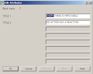
And this is what I achieved using the cursor
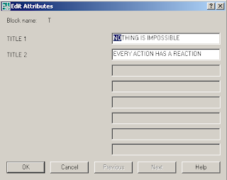
The image before moving the text

And this is what I achieved using the cursor

Tuesday, October 2, 2007
Renaming an Active Drawing from the Command Prompt
Is it really possible to rename an opened file? Normally the operating system will not allow you to do that. But it is REALLY possible to do it inside AutoCAD by adapting a tricky way as explained below. Here are the steps involved in the process.
- Get the new drawing name from the user
- Check any drawing is existing in the current folder with the name provided.
- If not, save and close the current drawing and copy it in the new drawing name.
- After verification, delete the old file.
- Open the copied file in AutoCAD
Though it seems like a long procedure, practically it all finish within a moment. The user never get the feeling of all those background processing. Users are encouraged to set system variable ISAVEBAK to 1 in order to eliminate the chances of possible data loss due to any unexpected errors. The following is an implimentation of above logic in AutoCAD VBA
'*****************************************************************
'<--  Active Drawing Renaming Utility                        -->
'<--  Renames the current drawing from the command prompt.   -->
'<--  By Mohamed Haris (zoomharis@gmail.com)                 -->
'*****************************************************************
Sub RenameOnline()
On Error GoTo ErrDet
Dim objFS, objFL As Object
Dim strFilePath As String, strNewFileName As String, strNewFileFullName As String
Set objFS = CreateObject("Scripting.FileSystemObject")
Set objFL = objFS.getfile(ThisDrawing.FullName)
strFilePath = ThisDrawing.Path
strNewFileName = ThisDrawing.Utility.GetString(True, vbCr & "Enter new file name to rename: ")
strNewFileFullName = strFilePath & "\" & strNewFileName & ".dwg"
'*** Check for a valid windows filename
If Not FileNameIsValid(strNewFileName) Then
    MsgBox "Please provide a valid name to rename....", vbExclamation
    GoTo ClearMem
ElseIf objFS.fileExists(strNewFileFullName) Then
    MsgBox "A file with new filename already exists...!!!" & vbCrLf & _
    "Please check the existing filenames...", vbExclamation
    GoTo ClearMem
Else
    ThisDrawing.Save
    objFL.Copy (strNewFileFullName), False
End If
'*** Make sure that the file has been copied before deleting the old one
If objFS.fileExists(strNewFileFullName) Then
    ThisDrawing.Close True
    objFL.Delete
    Application.Documents.Open strNewFileFullName
Else
    MsgBox "Couldn't rename the file. Please try again...!!!", vbExclamation
End If
ErrDet:
If Err.Number <> 0 Then
    MsgBox "An error occured while renaming the file....!!!" & vbCrLf & vbCrLf & _
    "Error Description: " & vbCrLf & Err.Description, vbExclamation
End If
ClearMem:
Set objFL = Nothing
Set objFS = Nothing
End Sub


'*** NOTE: A regular expression could serve better for this purpose
Function FileNameIsValid(ByVal strFileName As String) As Boolean
Dim i As Integer
If Trim(strFileName) = "" Then
    FileNameIsValid = False
    Exit Function
End If
arInvalidChars = Array("\", "/", ":", "*", "?", """", "<", ">", "")
For i = 0 To UBound(arInvalidChars) - 1
    If InStr(1, strFileName, arInvalidChars(i), vbTextCompare) <> 0 Then
        FileNameIsValid = False
        Exit Function
    End If
Next
FileNameIsValid = True
End Function
Normally I don't provide the new file name in the command prompt. Instead, there is another VBA routine which takes the the drawing name attribute value from the title blocks and provide it as the input for the RenameOnline utitlity. You could also implement this logic in any of your favourite programming languages.
Sunday, September 30, 2007
System Variables I Cannot Live Without - The Top Ten List
System variables have been one of the most important aspects of AutoCAD throughout its history.I wonder how complicated the life would have been without these tiny little masters. Here goes a few of them I cannot live without.
- FILEDIA - Suppresses display of the file dialog boxes. This is the culprit behind one of the most commonly asked questions by the newcomers about missing file dialog box.
- MIRRTEXT - Controls how the MIRROR command reflects text.Ignorance of this system variable may double your work at times.
- PICKFIRST - Controls whether you select objects before (noun-verb selection) or after you issue a command.For the beginners, I would suggest to keep the noun-verb selection off until they become familiar with the normal selection methods.
- LTSCALE - Sets the global linetype scale factor.It's required to be setup as per the drawing scale with each new drawing to get proper linetype display.
- DIMSCALE - Sets the overall scale factor applied to dimensioning variables that specify sizes, distances, or offsets.As in the case of LTSCALE variable, this is also required to be setup properly at the beginning of each new drawing to get proper dimension display.
- SNAPANG - Sets the snap and grid rotation angle for the current viewport relative to the current UCS.I often use this variable to draw something at a certain angle.
- EDGEMODE - Controls how the TRIM and EXTEND commands determine cutting and boundary edges.A must know variable for neat TRIM and EXTEND operations.
- ATTREQ - Determines whether the INSERT command uses default attribute settings during insertion of blocks.Setting it to 0 will avoid attribute prompts at the time of block insertion.
- MODEMACRO - Displays a text string on the status line, such as the name of the current drawing, time/date stamp, or special modes.Very interesting and powerful when DIESEL expressions are used inside.
- USERIx/Rx/Sx - Used for storage and retrieval of user-defined integer/real/string values. Very handy variables to store values for macro operations.
- ISAVEBAK
- DBLCLKEDIT
- FIELDEVAL
- DWGNAME
- DWGPREFIX
- CLAYER
- SDI
- HPGAPTOL
- MTEXTED
- REMEMBERFOLDERS
- STARTUP
- VTENABLE
- INSUNITS
- CTAB
- ZOOMFACTOR
Wednesday, September 26, 2007
Perform Loop Operations in AutoCAD LT using DIESEL
It's well known fact that you can not perform loop operations using DIESEL as you do in AutoLISP or other powerful programming languages. Isn't it really frustrating to have given up so many interesting tasks due to the absence of loop structures inside DIESEL? Let's give a try to stretch the LT limits a little bit and see how to mimic the loop operations using DIESEL.
The following macro illustrates how to use DIESEL to perfrom a loop operation. This macro calculates the factorial of a given number by iterating a required number of times. You can use the same logic to create various loop structures as per your requirement.
*^C^C$M=$(if,$(<=,$(getvar,USERI2),$(getvar,USERI1)),setvar;USERI3;$M=$(if,$(=,$(getvar,USERI2),1),1,$(*,$(getvar,USERI2),$(getvar,USERI3)));setvar;USERI2;$(+,$(getvar,USERI2),1),_modemacro;"The factorial of "$(getvar,USERI1)" is "$(getvar,USERI3);^C)
Before using the above macro, you need to run a simple macro to set up the user variables and the status bar. You need to supply the required number at the USERI1 prompt.
^C^C_modemacro;.;setvar;useri1;\;setvar;useri2;1;setvar;useri3;0;
Isn't it quite simple to do an iteration using DIESEL? Basically a loop macro has the following componetns.
- *^C^C in the beginning to have continuous operations
- A conditional statement using a counter variable to continuously check against the loop upper limit.
- If the condition is not met, do the required operations and continue.
- If the condition is met, then terminate the macro using ^C at the end.
Thursday, September 20, 2007
Total Area and Perimeter Calculation Macro
As a continuation to my previous post Total Length Calculation Macro for AutoCAD LT, here is another one to calculate total area and perimeter of selected objects. This macro has a few limitations.
1. You need to end the macro with a cancel (Esc) action.
2. The macro will be terminated upon picking up an object which doesn't have area.
3. Calculates area only by object method. Area calculation by continous picking of points are not supported.
Even after all these limitations, if you are interested, here goes the macro.
*^C^C_Area;O;\setvar;USERR1;$M=$(+,$(getvar,USERR1),$(getvar,AREA));setvar;USERR2;$M=$(+,$(getvar,USERR2),$(getvar,PERIMETER));_modemacro;"Total Area :"$(+,$(getvar,USERR1),$(getvar,AREA))", Total Perimeter :"$(+,$(getvar,USERR2),$(getvar,PERIMETER));
As in the case of length calculation macro, you need to use another macro for clearing the status bar and system variables.
^c^c_modemacro;.;setvar;USERR1;0;;USERR2;0;
Wednesday, September 19, 2007
Toggle AutoCAD Application Visibility
We can do a lot AutoCAD related programming outside AutoCAD using Windows Script Host. Some of the areas where windows scripting is useful are network management, windows registry manipulation, file or folder acces etc. Here is a sample VBScript code to toggle AutoCAD application visibility state.
Just copy the code and paste it inside notepad and save it with a vbs extension. Run the the file while AutoCAD is open. It will toggle the application display everytime you run it. Now you can leave your PC with peace of mind that nobody would interfere with your opened drawings.
On Error Resume Next
Set ObjACAD = GetObject(, "AutoCAD.Application")
If Err.Number <> 0 Then Err.Clear
    MsgBox "AutoCAD is not currently running...!!", vbExclamation
Else
    If ObjACAD.Visible = True Then
        ObjACAD.Visible = False
    Else
        ObjACAD.Visible = True
    End If
End If
Set ObjACAD = Nothing
Just copy the code and paste it inside notepad and save it with a vbs extension. Run the the file while AutoCAD is open. It will toggle the application display everytime you run it. Now you can leave your PC with peace of mind that nobody would interfere with your opened drawings.
Thursday, September 13, 2007


Saturday, September 8, 2007
Total Length Calculation Macro for AutoCAD LT
Before using the macro provided in this post, please note that this macro has not yet been tested in AutoCAD LT. I move forward based on the assumption that all the macro elements are acceptable in AutoCAD LT. Since I don't have LT with me, the testing part is left with the readers. This macro prompts the user to pick a first point and and second point repeatedly, and then displays the total distance in the AutoCAD status bar (Without using LISP). You have to use another simple macro to reset the settings before start using length calculation macro each time. Try the following macro and let me know whether it's useful.
*^C^C_dist;\\setvar;USERR1;$M=$(+,$(getvar,USERR1),$(getvar,DISTANCE));_modemacro;"Total Distance :"$(+,$(getvar,USERR1),$(getvar,DISTANCE));
Use the following macro to reset the status bar and system variable.
^c^c_modemacro;.;setvar;USERR1;0;
Now, you don't have to worry about drawing polylines to measure the the total distance. Most importantly, you can add distances from different locations, ie the pick points need not be continuous.
Saturday, September 1, 2007
Unleash the Double Click Power...
- The best thing I like in AutoCAD is the power of customization it offers for the end user. By doing so many customizations, you can convert your AutoCAD to a custom product most suitable for your industry. Moreover, the process of customization gets simpler with each new release of the product. Here is a sample tutorial to create a custom double click action which converts a Line to a PolyLine. Please have a look at the image attached below.

The picture itself speaks well about the process. Doesn't it? In case you are unable to make out the process, here goes the steps in detail. - Open CUI dialog by typing CUI in the command prompt (or Tools -->Customize -->Interface...).
- In the 'Command List' category, click on 'New' button to create a custom command (See the image section 1).
- Type in a name in the 'Name' property field (image section 2) and assign your macro to the 'Macro' property field (image section 3).
- Now the costom command is ready for use. The next thing is to apply this command to the double click action of an entity. For that, expand the 'Double Click Actions' category to locate the target entity (Here we are going to apply it to a 'Line').
- Drag the command using left mouse button and drop it right under the 'Line' category listed under the 'Double Click Actions' (image section 4). Before doing this, take a note of the existing command under the 'Line' category, in case you want to go back to the default command later.
- Now finish the process by clicking apply. Draw a line and double click on it to see how the new settings work. If the settings were done properly, the list command should list the object type as 'LWPOLYLINE'.

The double click macro for converting line to polyline is given below
^C^C$M=$(if,$(=,$(getvar,peditaccept),1),_pedit;,_pedit;;)
The following are some macros I use to make my drafting life easier.
Macro : ^C^C_xopen;
Category : XRef
Description : Opens the external reference source file.
Macro : ^C^C_dimedit;home;cmddia;0;_dimedit;new;<>;previous;;
Category : Dimension
Description : Regains its original dimension value, text position and text orientation
Macro: ^C^C$M=$(if,$(=,$(getvar,peditaccept),1),_pedit;decurve;,_pedit;;decurve;)
Category : Arc
Description : Converts an arc to a straight polyline
Macro: ^C^C$M=$(if,$(=,$(getvar,peditaccept),1),_pedit;close;,_pedit;;close;)
Category : Arc
Description : Converts an arc to a circular polyline
Macro: ^C^C_transparency;on;
Category : Image
Description : Makes an image transparent.
Macro: ^C^C'_.zoom;_o
Category : Applicable to all
Description : Zooms to the double clicked object
Macro: ^C^C_-view;_swiso;'_.zoom;_o;previous;;
Category : 3DSolid
Description : Switches to isometric view of the double clicked 3D object.
I have a few more useful double click actions. But I skip those for the reason that it contains LISP expressions which is not supported in AutoCAD LT. Please note that you can not directly do these things in AutoCAD 2005 or earlier versions. Hope you enjoyed the double click customizations. If you have got any double click actions with you, please feel free share it with me.
Thursday, August 23, 2007
Auto Increment Numbering Macro for AutoCAD LT
Have you ever tried automating tasks in AutoCAD LT? If so, you will find it really difficult due to lack of programming support inside it. Often this leads you to experiment with DIESEL to achieve the results you normally achieve in full version of AutoCAD. Here is a tricky macro to automate the process of increment numbering in AutoCAD LT.
*^c^c_text;\;;$M=$(+,$(getvar,USERR1),$(getvar,USERR2));setvar;USERR1;$M=$(+,$(getvar,USERR1),$(getvar,USERR2));
Configure the macro in a button (or wherever you are comfortable). Click on the button once and click on the required locations continuously to keep the incremented numbers. use USERR1 system variable to set the starting number and USERR2 for the increment. For example, suppose you need to start numbering from 1.001 and continue like 1.002,1.003,1.004........, set USERR1 to 1 and USERR2 to .001. This will enable you to do the numbering as stated before.
The above macro is restricted to work only when the text height in the current text style is 0. If you have the habit of assigning specific text height to a text style, then you should better use the following macro.
Quote:
*^c^c_text;\;$M=$(+,$(getvar,USERR1),$(getvar,USERR2));setvar;USERR1;$M=$(+,$(getvar,USERR1),$(getvar,USERR2));
I just removed only one semicolumn from the second macro after the 'Text' command. It's becuase the 'Text' command skips one step (Text height) if the current text style has already got text height assigned. Hope AutoCAD LT people find this tip very useful. Needless to say, it will give you the same result in AutoCAD full version.
*EDIT*
Thanks to a very good suggestion from Russ for adding a prefix, I ended up adding both prefix and suffix to the numbers.
*^c^c_text;\;;$M=$(getvar,USERS1)$M=$(+,$(getvar,USERR1),$(getvar,USERR2))$M=$(getvar,USERS2);setvar;USERR1;$M=$(+,$(getvar,USERR1),$(getvar,USERR2));
The macro uses USERS1 system variable to hold the prefix and USERS2 for the suffix. Thanks to comments from an anonymous visitor, I realised that USERSx system variables are not supported in AutoCAD LT. So I replaced the macro with a new one using (getenv,variable) function in place of (getvar,USERSx).
*^c^c_text;\;;$M=$(getenv,StrPrefix)$M=$(+,$(getvar,USERR1),$(getvar,USERR2))$M=$(getenv,StrSuffix);setvar;USERR1;$M=$(+,$(getvar,USERR1),$(getvar,USERR2));
You need to set two environment variables (I used StrPreifx for prefix and StrSuffix for suffix) using SETENV command which, I beleive, is available in AutoCAD LT. Don't forget to respect the text height of the current text style as mentioned eariler. Again, I don't have AutoCAD LT to test this macro. I would be really thankful if somebody could test it on LT and post a feedback on it.
*EDIT*
Sunday, August 19, 2007
Putting Everything Together - An Enhanced Line Command
I have experienced in the past that the best way to learn something new is to apply it in our own way. So it's time to apply whatever we have learned so far, in a practical way. The result is an enhanced line command which allows the user to change current layer and linetype on the fly. I have also tried to have logical seperations inside the code using reusable methods(See SetCurrentLayer, SetCurrentLType and CreateLine methods).
using Autodesk.AutoCAD.ApplicationServices;
using Autodesk.AutoCAD.Runtime;
using Autodesk.AutoCAD.EditorInput;
using Autodesk.AutoCAD.DatabaseServices;
using Autodesk.AutoCAD.Geometry;
namespace AcadNetSamples
{
public class Commands
{
/// <summary>
/// Enhanced Line Command.
/// Allows user to change current layer and
/// linetype from within the command.
/// </summary>
[CommandMethod("ELINE")]
public static void DrawEnhancedLine()
{
Document doc = Application.DocumentManager.MdiActiveDocument;
Database db = doc.Database;
Editor ed = doc.Editor;
PromptPointOptions prPO = new PromptPointOptions("\nPick start point of line : ");
prPO.AllowNone = true;
prPO.UseBasePoint = false;
PromptPointResult ppr;
ppr = ed.GetPoint(prPO);
//Get start point
Point3d SPoint = ppr.Value;
//Remeber it for the CLOSE option
Point3d CPoint = SPoint;
prPO.Keywords.Add("LAyer");
prPO.Keywords.Add("LType");
prPO.Keywords.Add("Close");
// Continue line command until the user interrupts
while (ppr.Status == PromptStatus.OK ppr.Status ==
PromptStatus.Keyword)
{
prPO.UseBasePoint = true;
//Use the previously picked point as the base point for new line
prPO.BasePoint = SPoint;
prPO.Message = "\nPick next point or ";
ppr = ed.GetPoint(prPO);
Point3d NPoint = ppr.Value;
if (ppr.Status == PromptStatus.OK ppr.Status ==
PromptStatus.Keyword)
{
//Exit command on enter key
if (ppr.Status == PromptStatus.None) break;
//Declare ObjectId variable for common use
ObjectId objID;
// Check to see whether any keyword is choosen
if (ppr.Status == PromptStatus.Keyword)
{
PromptResult prs;
switch (ppr.StringResult)
{
case "LAyer":
prs = ed.GetString("\nEnter a layer name to make it current: ");
if (prs.Status == PromptStatus.OK)
{
//Loop back on Enter
if (prs.StringResult == "")
continue ;
try
{
objID =
SetCurrentLayer(prs.StringResult);
//Check whether the operation was successful
if (objID != ObjectId.Null)
ed.WriteMessage("\nCurrent layer is '"
+ prs.StringResult+"'");
else
ed.WriteMessage("\nThe layer '" +
prs.StringResult + "' was not found.");
continue;
}
catch
{
ed.WriteMessage("\nUnable to change current
layer. An error occured...!!");
continue;
}
}
return ;
case "LType":
prs = ed.GetString("\nEnter a linetype name to make it current: ");
if (prs.Status == PromptStatus.OK)
{
//Loop back on Enter
if (prs.StringResult == "")
continue;
try
{
objID =
SetCurrentLType(prs.StringResult);
//Check whether the operation was successful
if (objID != ObjectId.Null)
ed.WriteMessage("\nCurrent linetype is "
+ prs.StringResult +"'");
else
ed.WriteMessage("\nThe linetype '"
+ prs.StringResult + "' was not found.");
continue;
}
catch
{
ed.WriteMessage("\nUnable to change current linetype. An error occured...!!");
continue;
}
}
return ;
case "Close":
try
{
objID =
CreateLine(SPoint, CPoint);
if (objID != ObjectId.Null)
return;
break;
}
catch {}
return;
}
}
try
{
objID = CreateLine(SPoint, NPoint);
//The last end point will serve as the next base point
if (objID != ObjectId.Null) SPoint = NPoint;
}
catch { return; }
}
}
}
private static ObjectId SetCurrentLayer(string LayerName)
{
ObjectId layerId=ObjectId.Null ;
Document doc = Application.DocumentManager.MdiActiveDocument;
Database db = doc.Database;
Editor ed = doc.Editor;
Autodesk.AutoCAD.DatabaseServices.TransactionManager tm = db.TransactionManager;
using (Transaction tr = tm.StartTransaction())
{
LayerTable lt = (LayerTable)tm.GetObject(db.LayerTableId, OpenMode.ForRead, false);
if (lt.Has(LayerName))
{
layerId = lt[LayerName];
db.Clayer = layerId;
}
tr.Commit();
}
return layerId;
}
private static ObjectId SetCurrentLType(string LineTypeName)
{
ObjectId ltypeId = ObjectId.Null;
Document doc = Application.DocumentManager.MdiActiveDocument;
Database db = doc.Database;
Editor ed = doc.Editor;
Autodesk.AutoCAD.DatabaseServices.TransactionManager tm = db.TransactionManager;
using (Transaction tr = tm.StartTransaction())
{
LinetypeTable ltt = (LinetypeTable)tm.GetObject(db.LinetypeTableId, OpenMode.ForRead, false);
if (ltt.Has(LineTypeName))
{
ltypeId = ltt[LineTypeName];
db.Celtype = ltypeId;
}
tr.Commit();
}
return ltypeId;
}
private static ObjectId CreateLine(Point3d SPoint,Point3d EPoint)
{
ObjectId lineId = ObjectId.Null;
Document doc = Application.DocumentManager.MdiActiveDocument;
Database db = doc.Database;
Editor ed = doc.Editor;
Line oLine = new Line(SPoint, EPoint);
Autodesk.AutoCAD.DatabaseServices.TransactionManager tm = db.TransactionManager;
using (Transaction tr = tm.StartTransaction())
{
BlockTable bt = (BlockTable)tm.GetObject(db.BlockTableId, OpenMode.ForRead, false);
BlockTableRecord btr = (BlockTableRecord)tm.GetObject(bt[BlockTableRecord.ModelSpace], OpenMode.ForWrite, false);
using (oLine)
{
lineId = btr.AppendEntity(oLine);
tm.AddNewlyCreatedDBObject(oLine, true);
}
tr.Commit();
}
return lineId;
}
}
}
Tuesday, August 14, 2007
Creating AutoCAD Geometry
I think it's time to get into AutoCAD geometry. So, in this session, we are going to create a line command . We will also see using prompt options in this sample code. The command name used here is DRAWLINE.
using Autodesk.AutoCAD.ApplicationServices;
using Autodesk.AutoCAD.Runtime;
using Autodesk.AutoCAD.EditorInput;
using Autodesk.AutoCAD.DatabaseServices;
using Autodesk.AutoCAD.Geometry;
namespace AcadNetSamples
{
public class Commands
{
[CommandMethod("DrawLine")]
public static void DrawLine()
{
Document doc = Application.DocumentManager.MdiActiveDocument;
Database db = doc.Database;
Editor ed = doc.Editor;
PromptPointOptions prPO = new PromptPointOptions("\nPick start point of line: ");
prPO.AllowNone = false;
prPO.UseBasePoint = false;
PromptPointResult ppr1 = ed.GetPoint(prPO);
if (ppr1.Status == PromptStatus.OK)
{
prPO.UseBasePoint = true;
prPO.BasePoint = ppr1.Value;
prPO.Message = "\nPick end point: ";
PromptPointResult ppr2 = ed.GetPoint(prPO);
if (ppr2.Status == PromptStatus.OK)
{
Point3d SPoint = ppr1.Value;
Point3d EPoint = ppr2.Value;
Line oLine = new Line(SPoint, EPoint);
Autodesk.AutoCAD.DatabaseServices.TransactionManager tm = db.TransactionManager;
Autodesk.AutoCAD.DatabaseServices.Transaction tr = tm.StartTransaction();
using
(tr)
{
BlockTable bt = (BlockTable)tm.GetObject(db.BlockTableId, OpenMode.ForRead, false);
BlockTableRecord btr = (BlockTableRecord)tm.GetObject(bt[BlockTableRecord.ModelSpace], OpenMode.ForWrite, false);
using
(oLine)
{
btr.AppendEntity(oLine);
tm.AddNewlyCreatedDBObject(oLine, true);
}
tr.Commit();
}
}
}
}
}
}
I don't want to confine this blog to learning AutoCAD.Net only. I have got some Tips & Tricks to share with you. You may encounter these in between the dotnet posts (If you see one, just understand that I didn't get enough time to learn next dotnet topic :-).
Saturday, August 11, 2007
AutoCAD Prompts & Error Handling
In this post, we are going to start with basic prompt operations and error handling. You will see samples on common AutoCAD prompts like string prompt, point prompt, distance prompt etc. The first sample in this session also covers very basic form of error handling. There are three commands (OPENDWG, DISPOINT & GETDIST) in the following code. The OPENDWG accepts a drawing path string input from the user and opens that drawing if exists. The DISPOINT prompts the user to pick a point and show the point value in the command prompt. The GETDIST prompts the user to pick two points and returns the distance between them. We will have a look at advanced prompt operations and creating AutoCAD geometry in the forthcoming sessions.
using Autodesk.AutoCAD.ApplicationServices;
using Autodesk.AutoCAD.Runtime;
using Autodesk.AutoCAD.EditorInput;
namespace AcadNetSamples
{
public class Commands
{
[CommandMethod("OPENDWG")]
public static void OpenDrawing()
{
Document doc = Application.DocumentManager.MdiActiveDocument;
Editor ed = doc.Editor;
PromptResult res = ed.GetString("\nEnter a drawing path: ");
if (res.Status == PromptStatus.OK)
{
try
{
Application.DocumentManager.Open(res.StringResult,false);
}
catch
{
ed.WriteMessage("\nUnable to open drawing file.");
return;
}
finally
{
ed.WriteMessage("\nThis is an AutoCAD.Net sample command.");
}
}
}
[CommandMethod("DISPOINT")]
public void DisplayPoint()
{
Editor ed = Application.DocumentManager.MdiActiveDocument.Editor;
PromptPointOptions prPO = new PromptPointOptions("Select a point: ");
PromptPointResult prPR = ed.GetPoint(prPO);
if (prPR.Status != PromptStatus.OK)
{
ed.WriteMessage("An error occured...!");
}
else
[CommandMethod("GETDIST")]
public void GetDistance()
{
Editor ed = Application.DocumentManager.MdiActiveDocument.Editor;
PromptDistanceOptions prDO = new PromptDistanceOptions("Select first point: ");
PromptDoubleResult prDR = ed.GetDistance(prDO);
if (prDR.Status != PromptStatus.OK)
{
ed.WriteMessage("An error occured...!");
}
else
using Autodesk.AutoCAD.ApplicationServices;
using Autodesk.AutoCAD.Runtime;
using Autodesk.AutoCAD.EditorInput;
namespace AcadNetSamples
{
public class Commands
{
[CommandMethod("OPENDWG")]
public static void OpenDrawing()
{
Document doc = Application.DocumentManager.MdiActiveDocument;
Editor ed = doc.Editor;
PromptResult res = ed.GetString("\nEnter a drawing path: ");
if (res.Status == PromptStatus.OK)
{
try
{
Application.DocumentManager.Open(res.StringResult,false);
}
catch
{
ed.WriteMessage("\nUnable to open drawing file.");
return;
}
finally
{
ed.WriteMessage("\nThis is an AutoCAD.Net sample command.");
}
}
}
[CommandMethod("DISPOINT")]
public void DisplayPoint()
{
Editor ed = Application.DocumentManager.MdiActiveDocument.Editor;
PromptPointOptions prPO = new PromptPointOptions("Select a point: ");
PromptPointResult prPR = ed.GetPoint(prPO);
if (prPR.Status != PromptStatus.OK)
{
ed.WriteMessage("An error occured...!");
}
else
{
ed.WriteMessage("The point is " + prPR.Value.ToString());
}
}
}
[CommandMethod("GETDIST")]
public void GetDistance()
{
Editor ed = Application.DocumentManager.MdiActiveDocument.Editor;
PromptDistanceOptions prDO = new PromptDistanceOptions("Select first point: ");
PromptDoubleResult prDR = ed.GetDistance(prDO);
if (prDR.Status != PromptStatus.OK)
{
ed.WriteMessage("An error occured...!");
}
else
{
ed.WriteMessage("Distance: " + prDR.Value.ToString());
ed.WriteMessage("Distance: " + prDR.Value.ToString());
}
}
}
}
}
}
}
Sunday, August 5, 2007
Iterations in C#
As I mentioned in the last post, in this session, we are going to cover the loop structures in C#. Our primary aim is to concentrate more on the syntax of loops. Here is a sample which shows iteration results in AutoCAD prompt using different looping methods.
using Autodesk.AutoCAD.ApplicationServices;
using Autodesk.AutoCAD.Runtime;
using Autodesk.AutoCAD.EditorInput;
namespace AcadNetSamples
{
public class Commands
{
[CommandMethod("LOOPS")]
public static void LoopOperations()
{
Document doc = Application.DocumentManager.MdiActiveDocument;
Editor ed = doc.Editor;
string[] strs = new string[10];
int i;
for (i = 0; i < 10; i++)
{
strs[i] = "String No. " + (i + 1).ToString();
}
ed.WriteMessage("\n\nUsing 'foreach' Loop\n");
foreach (string str in strs)
{
ed.WriteMessage("\n\t\t" + str);
}
ed.WriteMessage("\n\nUsing 'While' Loop\n");
i = 0;
while (i < 10)
{
ed.WriteMessage("\n\t\tString No. " + (i + 1).ToString());
i++;
}
ed.WriteMessage("\n\nUsing 'Do While' Loop\n");
i = 0;
do
{
ed.WriteMessage("\n\t\tString No. "+ (i + 1).ToString());
i++;
} while (i < 10);
}
}
}
Wednesday, August 1, 2007
Conditions forever
Before starting AutoCAD data specific programs, I would like to put my hands on C# language specific statements like If, Switch etc. Here is a sample program covering very basic condition checking and some output formatting. Next post, I shall try to cover looping in C#.
using Autodesk.AutoCAD.ApplicationServices;
using Autodesk.AutoCAD.Runtime;
using Autodesk.AutoCAD.EditorInput;
namespace AcadNetSamples
{
public class Commands
{
[CommandMethod("CONDITIONS")]
public static void ConditionalOperations()
{
Document doc = Application.DocumentManager.MdiActiveDocument;
Editor ed = doc.Editor;
int x = 1; int y = 2; int z = 3;
if ((x + y) == z) ed.WriteMessage("\n{0}+{1} is equal to {2}",x,y,z);
if ((z - y) != x)
{
ed.WriteMessage("\n{0}+{1} is not equal to {2}", z, y, x);
}
else
{
ed.WriteMessage("\n{0}-{1} is equal to {2}", z, y, x);
}
switch (x + y + z)
{
case 3:
ed.WriteMessage("\n{0}+{1}+{2}=3", x, y, z);
break;
case 4:
ed.WriteMessage("\n{0}+{1}+{2}=4", x, y, z);
break;
case 5:
ed.WriteMessage("\n{0}+{1}+{2}=5", x, y, z);
break;
default:
ed.WriteMessage("\n{0}+{1}+{2}={3}", x, y, z, (x + y + z));
break;
}
}
}
}
Try to experiment with the above code using different conditions. Also try to work with common logical operators like AND, OR etc. in your code.
Tuesday, July 31, 2007
Getting Started
Instead of spending time on discussing the concepts and theories behind AutoCAD.Net programming, I think we should better start with some sample code. It defenitely helps us to raise the confindence level. The thrill of watching our first program output in a new technology will defenitely last long and help us to gain momentum and energy for further exploration. So here goes our first program. Please remember that I am also a beginner in this field. So the code may not be of professional standard and may contain errors. I highly appreciate your suggestions for the improvement of these code snippets.
The following code displays a welcome message in the AutoCAD Text Editor window.
using Autodesk.AutoCAD.ApplicationServices;
using Autodesk.AutoCAD.Runtime;
using Autodesk.AutoCAD.EditorInput;
namespace AcadNetSamples
{
public class Commands
{
[CommandMethod("Hello")]
public static void SayHello()
{
Document doc=Application.DocumentManager.MdiActiveDocument;
Editor ed = doc.Editor;
ed.WriteMessage("\nHello and welcome to AutoCAD.Net world...!!");
}
}
}
Here goes a few thing to be taken care before you start using it.
The following code displays a welcome message in the AutoCAD Text Editor window.

Here is the a text version of the code if you want to copy and paste it in your editor. The above one is a screenshot from the code editor window. I used that image for a better understanding of the code. Once you copy the following code and paste it in Visual C# editor, it should arrange it in the manner shown above. So next post onwards, I may not include a screenshot.
using Autodesk.AutoCAD.ApplicationServices;
using Autodesk.AutoCAD.Runtime;
using Autodesk.AutoCAD.EditorInput;
namespace AcadNetSamples
{
public class Commands
{
[CommandMethod("Hello")]
public static void SayHello()
{
Document doc=Application.DocumentManager.MdiActiveDocument;
Editor ed = doc.Editor;
ed.WriteMessage("\nHello and welcome to AutoCAD.Net world...!!");
}
}
}
Here goes a few thing to be taken care before you start using it.
- You must have set reference to AutoCAD managed class libraries acmgd.dll and acdbmgd.dll . Otherwise the AutoCAD specific objects and methods will not get detected.
- If you are using Visual C# editor, then you can use Solution Explorer window to add reference to the above files. If you are using a command line version of compiler (CSC.EXE), then use /r option to set reference. (Type CSC/? in the command line to get help on compiler options)
- The project type has to be a Class Library in order to use it inside AutoCAD. If you start with VS Editor, the choose project template 'Class Library' in the beginning. If you use Command line, then choose /t:library option to compile it as a library project.
Those are the essentials and once you build the output, load the dll file (here AcadNetSamples.dll) from autocad using netload command. Type "Hello" in the command prompt and if everything goes right, you will see the following message.
"Hello and welcome to AutoCAD.Net world...!!"
Monday, July 30, 2007
AutoCAD.Net Programming - VB.Net or C# ?
As far as I have seen, the prerequisite for Dot Net programming is not the proficiency in any of the supporting languages, but a very good understanding of Dot Net Framework and Framework Class Libraries (FCL). There are several supporting languages (still counting) which enables you choose your favourite one. Of all those, the most popular ones are VB.Net and C#. Learning both of them seems to be a tough task (for me, even learning one of them seems to be a herculean task..!!). So I started searching on net for finding advantage of one over the other. I kept on reading till I saw these two links laying side by side in the same website.
Top 10 reasons VB.NET is better than C#
and
Top 10 reasons C# is better than VB.NET
Apparently, they all are same in case of productivity. Choosing a language depends mainly on how much the user is comfortable with it. Personally thinking, I had exposure to VBA and JavaScript in the past. In case of VB.Net, it is known as an entirely different language from VB. C# is a new language developed exclusively for Dot Net Framework. So the options are clear. Both are new languages and doesn't carry any benefits from learning its ancestors. Finally I decided to go for C# over VB.Net as it was becoming more popular among the Dot Net Developers. Moreover, some popular AutoCAD programmer blogs like Through the Interface (It's really a nice place) inspired me to choose C# over VB.Net. I found some very good DevHood training modules for beginners to start with C# and DotNet.
I found this training modules simple and elegant and good enough to give a start on C#. There are some advanced topics under the Training Modules link. I am planning to look at it when I get enough time to do so.
That's all about Microsoft.Net and C#. Now for doing AutoCAD.Net programming, we need to know something more than that. The easiest thing is to download AutoCAD 2007.Net Training.zip file from AutoCAD Developer Center. Go through the AutoCAD 2007 Managed C#.NET Training.3.doc and try it. If you come across any problems, visit forums like Autodesk AutoCAD.Net discussion group. There are many people out there to guide you through proper direction.
That's all I have done so far apart from doing a few basic programs. By the way, If you would like to download Microsoft Visual C# Express Edition (It's free) just follow the link.
Saturday, July 28, 2007
Hello World...!!
Hi,
My primary objectives are to learn, contribute and communicate knowledge, experience and wisdom with all of you. I beleive this blog will help me to accomplish that (ad?)venture. Mostly, I will be concentrating on AutoCAD Programming & Customization. That said, I will never hesitate to jump upon a subject, if I find it intersting and worth mentioning.
Thanks for visiting my blog.
:-)
Subscribe to:
Posts (Atom)

