It always make me wonder why the FILTER command is often overlooked by most of the AutoCAD users of current era, especially the newbies. It may be partially due to the fact that this command can get highly complicated at times depending upon the requirement. Ofcourse, it can be. But the power is always accompanied by complexity. Some of the advantages of this most powerful selection tool are;- Creating selection sets based upon multiple criteria
- Creating logical groups without physically grouping it
- Flexibility to use transparently in between the commands
To make it simple (sorry, if you find it otherwise ;-), let us go by a sample. I have a Piping & Instrumentation diagram in which I need to create a selection set of major and minor process lines along with the line numbers. The newbie designer has drawn some of the lines as LINE entity and rest of them as POLYLINE entity. All the major lines are placed inside 'MAJOR' layer and the minor ones in 'MINOR' layer. The line number is placed inside an attributed block reference named 'LINENO' which resides in 'LINE_NUM' layer. The image below illustrates the filter criteria for creating the above selection set.
 This is a nested filter criteria that makes it little difficult to understand. Nothing to worry. Let us split it into smaller portions so that we can analyse it easily.Following is the description of each portion in the order as shown in the image.
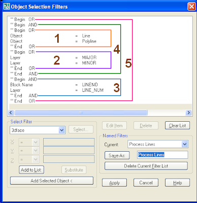
- Object= 'LINE' OR 'POLYLINE'
- Layer = 'MAJOR' OR 'MINOR'
- Block_Name = 'LINENO' AND Layer = 'LINE_NUM'
- Result of Step-1 AND Step-2
- Result of Step-3 AND Step-4.
If you represent the whole thing as a logical expression, it would look like the following statement;
((( Object= 'LINE' OR 'POLYLINE') AND (Layer = 'MAJOR' OR 'MINOR')) OR (Block_Name ='LINENO' AND Layer = 'LINE_NUM'))
If you have a closer look at the filter, you will find that the innermost criteria gets resolved first and passes its result to the outer ones in nested filters. In the above case, the criteria to be executed at the final stage is the outermost one (Step-5).
This way, you can save very complex filters in your drawing for quick access at any stage of drawing development or review.


