Have you had the habit of working on isometric drawings frequently? I do a lot of isometric drawings during my work. While doing these drawings, you may need to switch between rectangular and isometric snaps several times. Here is a simple macro to easily switch between these snap modes.
^C^C_setvar;SNAPSTYL;$M=$(if,$(=,$(getvar,SNAPSTYL),0),1,0)
I found a similar macro commented by Kate Morrical in her own blog LT Unlimited. Here goes Kate's version.
$M=$(if,$(=,$(getvar,SNAPSTYL),1),SNAPSTYL;0;;,SNAPSTYL;1;;)
Thanks Kate, for the handy macro.
Showing posts with label Tips 'n' Tricks. Show all posts
Showing posts with label Tips 'n' Tricks. Show all posts
Monday, March 21, 2011

Friday, November 26, 2010
Sharing Raster Files? Convert Them to Easily Viewable Formats Using Autodesk Design Review
Here is another reason for you to have Autodesk Design Review installed on your desktop. In a previous post, you saw how to use Autodesk Design Review as your default viewer for raster files. What if somebody else – for example, somebody from top management or a subcontractor - who doesn’t have Autodesk Design Review or any other raster file viewers installed on their system wants to review the raster design files? Don’t worry about installing the viewers everywhere. We can easily convert these files to PDF or TIF files using Autodesk Design Review.
Open Autodesk Design Review application on your desktop. Make sure that the ‘List View’ and ‘Thumbnails’ palettes are switched on in the ‘Show/Hide Palettes’ ribbon menu.

Open windows explorer and select raster files you wish to convert (use Ctrl+A for in case want you select all the files in the folder).

Now drag and drop them inside the ‘List View’ window / Thumbnail window.

You can drag the files inside the list view to arrange them in the proper order.

Use the ‘Thumbnail’ tab, if you want to preview while arranging them in order.

Select all the files in the ‘List View’ or ‘Thumbnails’ palette and right click to choose ‘Print’ option in the popup menu.

In the print dialog box, select the PDF writer of your choice (I use CutePDF writer which is really nice and free). Your can also use common printers like ‘Microsoft Document Image Writer’ to get a multipage TIF document output. Don’t forget to select ‘Choose paper source by DWF page size’ in the ‘Page Handling' section, if you want to preserve original sheet sizes. The print range will be selected ‘All’ by default. Ignore the print range shown in the image as I selected ‘Current sheet only’ option by mistake while taking the snapshot :-).

That’s it. Now your uncommon raster file formats are ready to be shared with most of the people around you. Trust me; Autodesk Design Review is worth more than a free design review application. Go and grab it right now from Autodesk site for free of cost!
Monday, October 11, 2010
An Easy Way to Publish Drawings from Different Folders
How do you publish drawings from different folders? Do you navigate to each folder from the publish dialog box for selecting files? That sounds really painful. Don’t worry; a simple drag and drop trick can ease your pain.
I will show you the method to accomplish this with the help of a sample folder structure. The following image shows a sample root folder with 5 different project folders.

Each folder contains different drawing files. For publishing all the drawings in a single stretch, follow the steps as given below.
- Click on the root folder (‘Sample’ in this case) and hit the search button on the toolbar.
- Type *.dwg to list all the drawings under the root folder and subfolders.

- Invoke the publish dialog box inside AutoCAD.
- Press Ctrl+A to select all files or use Ctrl/Shift + Left Mouse Click to select only desired files in the explorer search window.
- Now drag and drop the selected files to the publish dialog box. That’s it! You are done with selecting multiple files from multiple folders.

Try that and you will come to know that it is as simple as any other AutoCAD drag & drop operations.
Thursday, July 15, 2010
A Quick Tip on Publishing Drawings into Individual PDF Files
Recently our designers came across a requirement of publishing drawings into individual PDF files. For those who don’t know, here is the main setting you have to remember while publishing PDF files.
- Click on ‘Publish Options’ button inside the Publish dialog box.
- Inside the Publish Options window, select type as ‘Single-sheet file’ instead of ‘Multi-sheet file’ in the ‘General DWF/PDF options’ as shown in the image below.

Rest of the publish settings shall be same as publishing multiple PDF files. This tip might be familiar to most of you. Well, I have another tip for you to handle post publish PDF file names using windows command prompt. Using REN command with a combination of wildcard characters, you can easily rename the PDF files to standard names. For example, you would like to rename ‘Drawing_xxx-Model.pdf’ file to ‘Drawing_xxx.pdf’ format where xxx stands for unique characters. Here is the command for the above scenario.
REN *_???-Model.pdf *_???.pdf

As you can see in the above image, the file names have been modified using a single command line. The wildcard combination may vary from case to case. Have a look at windows commands and command prompt if you have not yet experimented with it. It will definitely help you to handle your day-to-day tasks easily and comfortably.
Friday, August 28, 2009
Quick Tip - Start an MText List with a Number or Alphabet of Your Choice
Last week I came across one of our designers using this nice trick and thought I would share it with you people. If you want to start a list inside MText window with a number or alphabet of your choice, try the following steps.
 In addition to that, a little research on the subject helped me to prefix the list numbers with a custom text, as shown in the image below.
- Type the number or alphabet followed by a period (dot) symbol.
- Press the tab button after the period symbol
- Type the content of the first line (optional) and press enter key.
That's it. Now you will find the list starting with the number or alphabet you typed over there. Shown below is a sample list created using the above steps.
 In addition to that, a little research on the subject helped me to prefix the list numbers with a custom text, as shown in the image below.
Wednesday, August 12, 2009
Quick Tip - Generating a Drawing List from Different Folders Using Windows Command Prompt
Most you might already know that typing DIR *.dwg /B > ListFileName in the windows command prompt will provide you with a quick list of drawings in the specific location. What if you want to create a list with drawings from multiple folders? It's a really simple task. See the following sample to get to know the syntax.
DIR D:\Proj_Dir\Disc-1\*.dwg D:\Proj_Dir\Disc-2\*.dwg D:\Proj_Dir\Disc-3\*.dwg /B > D:\Proj_Dir\Dwg_List.txt
As you can see, the paths are seperated by a space. Remember that the /B switch is still required to get the bare format file names. The above command will list all the drawing file names in the folders Disc-1, Disc-2 and Disc-3 to the Dwg_List.txt file. To access windows command prompt, either type CMD in the run prompt or locate it via Start--> All Programs --> Accessories --> Command Prompt.
DIR D:\Proj_Dir\Disc-1\*.dwg D:\Proj_Dir\Disc-2\*.dwg D:\Proj_Dir\Disc-3\*.dwg /B > D:\Proj_Dir\Dwg_List.txt
As you can see, the paths are seperated by a space. Remember that the /B switch is still required to get the bare format file names. The above command will list all the drawing file names in the folders Disc-1, Disc-2 and Disc-3 to the Dwg_List.txt file. To access windows command prompt, either type CMD in the run prompt or locate it via Start--> All Programs --> Accessories --> Command Prompt.
Tuesday, July 14, 2009
How to Use DWG TrueView to Optimize Your Drawing Files
Yet another reason to add DWG TrueView to your arsenal. DWG TrueView can be used as an excellent tool to optimize drawing files in batch. With facilities like purging, auditing, xref binding etc. TrueView has become truly irresistible for the CAD managers/administrators/users . Following are the steps involved in the process.
1. Start DWG TrueView and open 'DWG Convert' from the menu. It will launch the 'DWG Convert' dialog box.
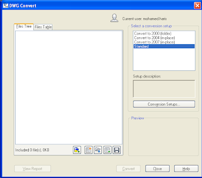
2. Click on the 'Conversion Setups' button to open 'Conversion Setups' dialog box. Our idea is to create an exclusive setup for our optimization process.
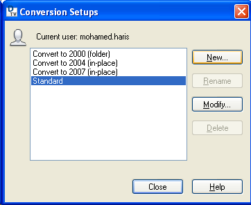
3. Click on 'New' button to launch 'New Conversion Setup' dialog box and provide a meaningful name over there.
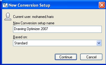
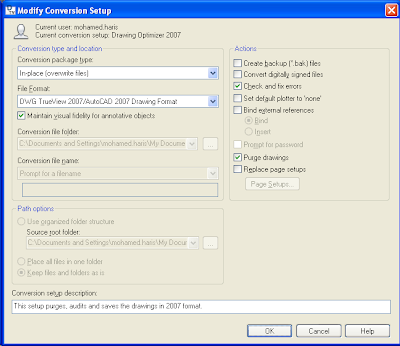
4. Clicking on 'Continue' button will pop up the 'Modify Conversion Setup' dialog box. Here I am going to use the basic settings. You may choose the options as per your requirement. Since our aim is to optimize the drawings (drawing format conversion is not our primary objective), I prefer to use 'In-place (overwrite files)' as my conversion package type. Choose the drawing file format based upon your company/client CAD standards (We normally use AutoCAD 2007 format as we are still on AutoCAD 2008). In the actions area, select 'Check and fix errors' and 'Purge drawings' check boxes as a minimum. Don't forget to provide a conversion setup description at the bottom in order to easily make out the setup objective later on.
5. Click 'Ok' to finalise the setup. You can see the new setup name listed in the 'Conversion Setups' list box.
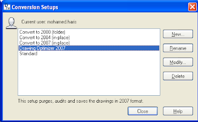
6. Close the dialog box to go back to the 'DWG Convert' dialog box. Add the drawing files to be optimized using the 'Add file' button in the bottom side. Once the drawings have been added, make sure that the recently created conversion setup is selected in the list. That's it. Just click on convert button and the TrueView application will do the rest for you.
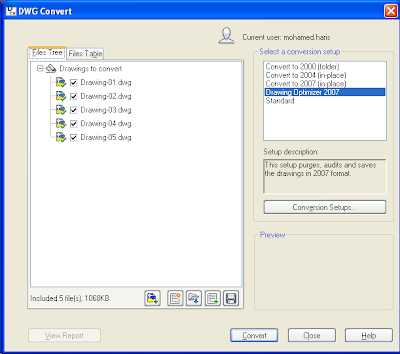
Once the setup is made, you can use the same setup every time you need to optimize the drawings. Really cool, isn't it? The entire process consumes only a little time and resources. In case you haven't installed AutoCAD 2010 yet, TrueView is a must for you as it can bring 2010 format files down to your AutoCAD version compatible format. What else you need to get it installed on your system? DWG TrueView and Autodesk Design Review are FREE and can be downloaded from the Autodesk site.
1. Start DWG TrueView and open 'DWG Convert' from the menu. It will launch the 'DWG Convert' dialog box.

2. Click on the 'Conversion Setups' button to open 'Conversion Setups' dialog box. Our idea is to create an exclusive setup for our optimization process.

3. Click on 'New' button to launch 'New Conversion Setup' dialog box and provide a meaningful name over there.

4. Clicking on 'Continue' button will pop up the 'Modify Conversion Setup' dialog box. Here I am going to use the basic settings. You may choose the options as per your requirement. Since our aim is to optimize the drawings (drawing format conversion is not our primary objective), I prefer to use 'In-place (overwrite files)' as my conversion package type. Choose the drawing file format based upon your company/client CAD standards (We normally use AutoCAD 2007 format as we are still on AutoCAD 2008). In the actions area, select 'Check and fix errors' and 'Purge drawings' check boxes as a minimum. Don't forget to provide a conversion setup description at the bottom in order to easily make out the setup objective later on.

5. Click 'Ok' to finalise the setup. You can see the new setup name listed in the 'Conversion Setups' list box.

6. Close the dialog box to go back to the 'DWG Convert' dialog box. Add the drawing files to be optimized using the 'Add file' button in the bottom side. Once the drawings have been added, make sure that the recently created conversion setup is selected in the list. That's it. Just click on convert button and the TrueView application will do the rest for you.

Once the setup is made, you can use the same setup every time you need to optimize the drawings. Really cool, isn't it? The entire process consumes only a little time and resources. In case you haven't installed AutoCAD 2010 yet, TrueView is a must for you as it can bring 2010 format files down to your AutoCAD version compatible format. What else you need to get it installed on your system? DWG TrueView and Autodesk Design Review are FREE and can be downloaded from the Autodesk site.
Tuesday, July 7, 2009
DATAEXTRACTION Means A Lot More Than Simple Attribute Extraction
How often do you use DATAEXTRACTION wizard for extracting some information other than block attribute data? I have often seen people leaving it behind for tasks like extracting specific text information mentioning that this tool is not powerful enough to get an accurate output. That's not true. Here I am going to show you how to extract a line list from a bunch of Piping & Instrumentation Diagrams (P&ID). The P&IDs contains a lot of other text objects. But with the help of some filtering options, you can extract only the required text information from the drawing.
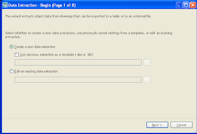
1. Start DATAEXTRACTION wizard
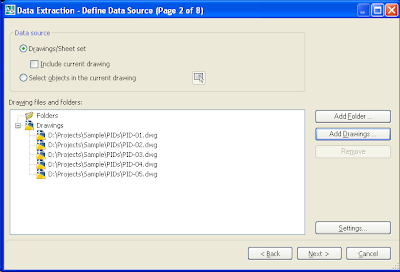
 2. Select the required P&ID drawings (Here I am using sample ones).
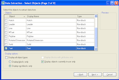
 3. In the third page select only 'Text' as object type.(Tip: You can uncheck all entries simultaneously by using right click).
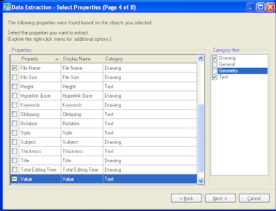
 4. In the fourth page, select 'Drawing' and 'Text' in the category filter. Also select 'File Name' and 'Value' in the properties area.
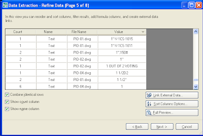
 5. In the refine data page, you will get a screen similar to the one shown below. This is the area where we are going to play our game. You will notice that the value field contains various text object values from different drawings. We need to confine the list to line numbers.
 6. Now right click on the value column and select 'Filter Options' from the right click menu.
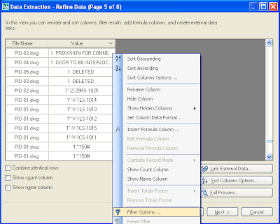 7. You will be provided with a filter dialog box as shown in the image below. For our purpose, select the 'Contains' list item from the first list box and type in a wildcard criteria *"-* in the second list box as shown in the picture.
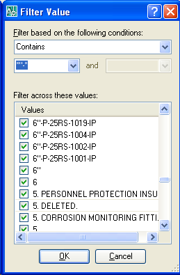 8. Click 'Ok' to apply the filter. Now you can see the value column filtered to show only line numbers based upon the given criteria.
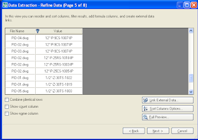 9. Click on 'Next' button and save the output as an excel file or table.
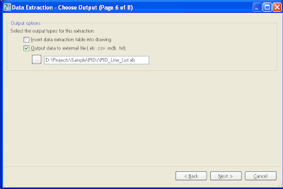
You can easily create various lists from your drawings irrespective of the data containers. Whether it be attribute or text, DATAEXTRACTION is powerful enough to pull the required data based upon different conditions. As the wildcard criteria plays a critical role in extracting the specific data, you need to be very careful to choose the right criteria in order to get proper results.
On a side note, I feel like the command name is a bit too long. It would be a lot better if it were something like DATAXTRACT or even shorter. Anyway, that's not a matter of a concern as we don't use this command very frequently.
1. Start DATAEXTRACTION wizard
 2. Select the required P&ID drawings (Here I am using sample ones).
 3. In the third page select only 'Text' as object type.(Tip: You can uncheck all entries simultaneously by using right click).
 4. In the fourth page, select 'Drawing' and 'Text' in the category filter. Also select 'File Name' and 'Value' in the properties area.
 5. In the refine data page, you will get a screen similar to the one shown below. This is the area where we are going to play our game. You will notice that the value field contains various text object values from different drawings. We need to confine the list to line numbers.
 6. Now right click on the value column and select 'Filter Options' from the right click menu.
 7. You will be provided with a filter dialog box as shown in the image below. For our purpose, select the 'Contains' list item from the first list box and type in a wildcard criteria *"-* in the second list box as shown in the picture.
 8. Click 'Ok' to apply the filter. Now you can see the value column filtered to show only line numbers based upon the given criteria.
 9. Click on 'Next' button and save the output as an excel file or table.
You can easily create various lists from your drawings irrespective of the data containers. Whether it be attribute or text, DATAEXTRACTION is powerful enough to pull the required data based upon different conditions. As the wildcard criteria plays a critical role in extracting the specific data, you need to be very careful to choose the right criteria in order to get proper results.
On a side note, I feel like the command name is a bit too long. It would be a lot better if it were something like DATAXTRACT or even shorter. Anyway, that's not a matter of a concern as we don't use this command very frequently.
Wednesday, April 15, 2009
How To Use Autodesk Design Review As Your Default Raster Image Viewer
Have you had a lot of headache in the past for viewing raster files those are not supported by windows built in image viewer applications? Don't worry, the solution is right under your nose. Apart from serving as an excellent review application, Autodesk Design Review can also be used as a raster image viewer. That means, you don't have to attach the raster images inside AutoCAD to view the contents. Instead, you can directly double click it on the explorer so that it opens directly in the Design Review application. Please make sure that you have done the following steps.
1. Goto Control Panel and double click on 'Folder Options'.
2. Goto the 'File Types' tab.
3. Locate the raster file extension inside the 'registered file types' list
4. If the extension does not exist, then click on 'New' to create a new one.
1. Goto Control Panel and double click on 'Folder Options'.
2. Goto the 'File Types' tab.
3. Locate the raster file extension inside the 'registered file types' list
4. If the extension does not exist, then click on 'New' to create a new one.
 5. Select the extension from the list and click on 'Change' button shown in the details section.

6. From the next popup window, choose 'Select the program from a list' option.
 7. Choose Autodesk DWF Application as the preferred application to open files with this extension. Also remember to check the 'Always use the selected program to open this kind of file' check box shown right under the list.

8. If everything is done properly, it will look as shown in the image below.

That's it. Repeat the same steps for other types of raster files. Once done, you don't have worry about it any more. Now you can goto explorer and double click those files to open it directly inside the Design Review application. I have configured mine to view file types like CAL, CALS, GP4, CG4, MIL, RST, PCT, PICT, TGA, RLS etc. (testing pending for some types). The best part of the story is that you can easily save this image as a DWF(x) file in order to send it to somebody for review purpose.
Autodesk Design Review is a wonderful review application with exciting features like '2D content comparison', 'PDF Support' etc. It's free and can be downloaded from the Autdesk Design Review site.
Sunday, January 25, 2009
Assigning Multiple Double Click Actions to Single Entity Type in AutoCAD
In the Unleash the Double Click Power post, you saw how to customize the double click action of an entity type to implement custom double click actions. Now we are going to see how we can implement different double click actions simultaneously on single entity type. Normally, we accomplish this by using Reactors or Events in the respective languages. But, we are not going to use any of these in our method. Rather, we will follow a tricky way to achieve the same result.
As an example, I will show you how to change the double click action of an 'Attribute Block'. Normally double clicking an attribute block shows the Enhanced Attribute Editor Dialog. We are going to change this to show either Enhanced Attribute Editor(_eattedit) or Edit Attributes dialog (_attedit) depending on certain condition. Let's say, when we double click on a title block named TITLE_BLOCK, it should display the Enhanced Attribute Editor dialog and for all other blocks in the drawing, it should display Edit Attributes dialog. The step by step configuration is given below.
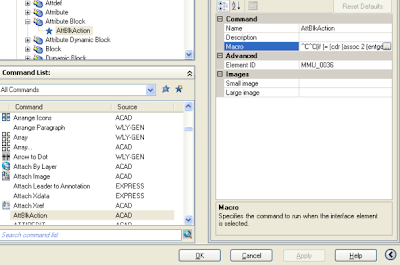
As an example, I will show you how to change the double click action of an 'Attribute Block'. Normally double clicking an attribute block shows the Enhanced Attribute Editor Dialog. We are going to change this to show either Enhanced Attribute Editor(_eattedit) or Edit Attributes dialog (_attedit) depending on certain condition. Let's say, when we double click on a title block named TITLE_BLOCK, it should display the Enhanced Attribute Editor dialog and for all other blocks in the drawing, it should display Edit Attributes dialog. The step by step configuration is given below.
- Open CUI and create a custom command with the following code inside the macro section of the command. If you don't know how to create a custom command, then refer to the 'Unleash the Double Click Power' post mentioned above. Replace the 'TITLE_BLOCK' inside the following code with your actual title block name.
^C^C(if (= (cdr (assoc 2 (entget (ssname (ssget "P") 0)))) "TITLE_BLOCK") (command "_eattedit")(command "_ddatte" )) - Drag and drop the custom command under the 'Attribute Block' section inside the Double Click Actions.
- Click on 'Apply' and close the CUI dialog.

That's it. Now if you double click on the title block, it will open the Enhanced Attribute Editor dialog and for all other attributed blocks, it will open Edit Attributes dialog. By the way, don't forget to take a backup of the default CUI files before you start experimenting with them.
Sunday, January 18, 2009
Quick Tip - A Shortcut for Closing Active Drawing
You already know that ALT+F4 can effectively be used to quit a running application in windows operating system. For those who don't know, pressing CTRL+F4 inside AutoCAD will close the active drawing without touching the application or other drawings already open over there. Though it's a more straight forward shortcut than the ALT+F+C, I would like to stick to the latter as it looks easier to me (May be because I am used to that). CTRL+F4 shortcut is not limited to AutoCAD, but it works well with almost all windows multi document interface (MDI) applications.
Wednesday, November 19, 2008
Developing a Sine Wave Generator using DIECAL
In the last post, we saw how easiy we could accomplish complicated operations using DIECAL. Further to that, we are going develop a sine wave generator using a few lines of code. I know that you don't have a sine wave generator even in your wildest DIESEL dreams. But it is a really simple task using DIECAL. Once again, I am going to use points in order to make it simple. For generating sine wave, use the following macro.
*^C^C_setvar;userr1;$M=$(+,$(getvar,userr1),$(getvar,userr2))$(if,$(>=,$(*,$(+,$(getvar,userr1),$(getvar,userr2)),10),$(*,$(getvar,userr3),360)),^C)_Point;'CAL;[$(getvar,userr4)+$(+,$(getvar,userr1),$(getvar,userr2))/18,sin(10*$(+,$(getvar,userr1),$(getvar,userr2)))];
The above macro makes use of USERR1 to USERR4 system variables. The USERR1 and USERR2 values are automatically set by the set/reset macro (given below). USERR3 holds the value for number of cycles created and USERR4 is for X axis lag value (See the sample image). Use the following macro to set/reset initial values. When you run this macro, just follow the status bar messages.
^C^C_setvar;userr1;-1;;userr2;1;userr3;1;_modemacro;Enter number of cycles:;userr3;\userr4;0;_modemacro;Enter lag value for X axis:;setvar;userr4;\_modemacro;.;
The following image illustrates three sine waves gererated with a cycle value of 3 and X axis lag value 0 (Red) .22 (Green) and .44(Yellow).

*^C^C_setvar;userr1;$M=$(+,$(getvar,userr1),$(getvar,userr2))$(if,$(>=,$(*,$(+,$(getvar,userr1),$(getvar,userr2)),10),$(*,$(getvar,userr3),360)),^C)_Point;'CAL;[$(getvar,userr4)+$(+,$(getvar,userr1),$(getvar,userr2))/18,sin(10*$(+,$(getvar,userr1),$(getvar,userr2)))];
The above macro makes use of USERR1 to USERR4 system variables. The USERR1 and USERR2 values are automatically set by the set/reset macro (given below). USERR3 holds the value for number of cycles created and USERR4 is for X axis lag value (See the sample image). Use the following macro to set/reset initial values. When you run this macro, just follow the status bar messages.
^C^C_setvar;userr1;-1;;userr2;1;userr3;1;_modemacro;Enter number of cycles:;userr3;\userr4;0;_modemacro;Enter lag value for X axis:;setvar;userr4;\_modemacro;.;
The following image illustrates three sine waves gererated with a cycle value of 3 and X axis lag value 0 (Red) .22 (Green) and .44(Yellow).

Thursday, October 16, 2008
A Shortcut for Jumping over Words in AutoCAD
This method works fine almost everywhere in windows; be it a word processor, text editor or a dialog prompt. But I thought it would be really interesting to the AutoCAD people who normally deal with a lot of text in day to day life.
You can use CTRL + Right Arrow key to move to the next word or CTRL + Left Arrow key to move to the previous word while you are editing text inside AutoCAD. It successfully worked wherever I tried including Edit Text dialog box, Edit Attributes dialog box, MText Editor and Enhanced Attribute Editor. You can also use CTRL + Up/Down arrows to move to the beginning and end of a MText paragraph.
Thanks to Digital Inspiration for the tip. By the way, I am going back home on vacation for the next three weeks and might not be spending time in front of the computers during the period. Hope to post some good stuff after the trip with the help of a 'refreshed mind' ;-)
You can use CTRL + Right Arrow key to move to the next word or CTRL + Left Arrow key to move to the previous word while you are editing text inside AutoCAD. It successfully worked wherever I tried including Edit Text dialog box, Edit Attributes dialog box, MText Editor and Enhanced Attribute Editor. You can also use CTRL + Up/Down arrows to move to the beginning and end of a MText paragraph.
Thanks to Digital Inspiration for the tip. By the way, I am going back home on vacation for the next three weeks and might not be spending time in front of the computers during the period. Hope to post some good stuff after the trip with the help of a 'refreshed mind' ;-)
Tuesday, September 9, 2008
Advanced Drag & Drop Operations - Link to a Specific Excel Cell or Range
Have you ever tried linking an AutoCAD object to a specific cell or row? For example, you might want to link a door block with a specific row inside the door schedule. Follow the easy steps to accomplish the task.
- Keep the Excel file and the drawing open.
- Select the required cell by clicking on it.
- Move the cursor towards the side of the cell until you see the move symbol (Similar to what you see inside the lens in zoom extents button icon).
- Now right click and drag the cell to the AutoCAD window.
- On releasing the right mouse button, you will be provided with a menu containing a menu item 'Create hyperlink here' as shown below.
 You can modify the above link to select a range of cells instead of a single cell.Press Ctrl+K and select the previous AutoCAD entity to open 'Edit Hyperlink' dialog box. At the end of the link, you will see something like file name.xls#sheet name!cell number. For example, suppose you are linking the C3 cell of Sheet1 of Test.xls placed in C: drive, then the link path will be C:\Test.xls#Sheet1!C3. In order to link a range of cells, you have to modify the above syntax to file name.xls#sheet name!cell number1:cell number2. ie, in the above example, it will become C:\Test.xls#Sheet1!C3:E6 to link a range of C3:E6.
Try to link a word paragraph using the above method and let me know how you achieved the desired result.
Advanced Drag & Drop Operations - Load / Run Scripts / LISP / VBA / ARX
Depending upon the type of files, there may be slight variations in the drag & drop result. Let's see how each file type responds.
Script: If you drag and drop a script file into the autocad window, it executes the script.
LISP: If you drag and drop a file containing LISP expressions but not a function definition, it straight away executes the LISP expressions. If the file consists of any LISP function definitions, it loads the functions into AutoCAD.
VBA: If you drag and drop a DVB file, it loads that project. The VBA module files (BAS extension) doesn't support drag and drop loading.
ARX: Loads the specific ARX application.
You can also use the drag and drop method to load other customization files like CUI, MNS etc.
Script: If you drag and drop a script file into the autocad window, it executes the script.
LISP: If you drag and drop a file containing LISP expressions but not a function definition, it straight away executes the LISP expressions. If the file consists of any LISP function definitions, it loads the functions into AutoCAD.
VBA: If you drag and drop a DVB file, it loads that project. The VBA module files (BAS extension) doesn't support drag and drop loading.
ARX: Loads the specific ARX application.
You can also use the drag and drop method to load other customization files like CUI, MNS etc.
Thursday, September 4, 2008
Advanced Drag & Drop Operations - Insert & Link Raster Images
Do you know the easiest way to attach an image? It's a simple drag (left click) and drop from windows explorer to AutoCAD drawing. Let's see how to link a an external image to an attached image. For example, you might want to link an overall plot plan image to a plot plan . For that, right click and drag the destination image to the drawing. When you drop it there, you will find a menu with 'Create hyperlink here' as shown below.
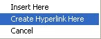 Click on that and select the attached image when prompted for selection. To test the link, hold down the Ctrl key and click on the image.
 Click on that and select the attached image when prompted for selection. To test the link, hold down the Ctrl key and click on the image.
Advanced Drag & Drop Operations - Copy Text from a Web Page / MS Outlook / Text File
This time we will see how to copy text from a web page, Outlook and a text file.
To copy text from a text file
To copy text from a text file, left click the text file from explorer window, then drag and drop it to the host drawing.
To copy text from web page or outlook
Open the web page or email, then highlight required portion of text then drag and drop it into AutoCAD window.
In both the cases, it will be copied as MText.
To copy text from a text file
To copy text from a text file, left click the text file from explorer window, then drag and drop it to the host drawing.
To copy text from web page or outlook
Open the web page or email, then highlight required portion of text then drag and drop it into AutoCAD window.
In both the cases, it will be copied as MText.
Advanced Drag & Drop Operations - Attach a Drawing as an External Reference
As a continuation of previously posted drag & drop operations (Move Text Inside Edit Text Dialog and Move Text Inside Edit Attributes Dialog), we are going to look into some more intersting ones. You already know that dragging a DWG file into empty AutoCAD application window opens that file over there and in case any drawings are already open there,it inserts the dragged drawing as a block. Apart from this, if you need to attach the drawing file as an external reference, follow the steps given below.
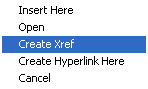
- Locate the drawing file to be attached inside explorer window.
- Right click and drag the file into the host drawing already opened in AutoCAD.
- When you leave the right mouse button, you will see a menu as shown below. Choose 'Create Xref' from the menu.

That's it. Now you have the dragged drawing attached as an external reference. We will see more drag & drop operations in the next posts.
Wednesday, August 20, 2008
A Special Break Utility for AutoCAD LT People Using DIESEL
This is an attempt to mimic the AutoLISP/VBA functionality in AutoCAD LT using DIESEL.This macro prompts the user for an intersection point and breaks the intersecting objects like Line, Polyline, Arc, SPline equally from either sides. The break gap can be adjusted using the USERR1 system variable. If you don't provide any value to the USERR1 system variable, it cuts the line at the intersection point without leaving any gap in between. Before having a look at the macro, let me remind you that the macro has not been tested in AutoCAD LT (as usual) because there is no AutoCAD LT with me because there is no need to use AutoCAD LT because there is Vanilla AutoCAD with me. Here goes the macro.
*^C^C_setvar;osmode;0;ucs;object;int;\Break;$M=$(getvar,lastpoint);F;
@$(getvar,userr1)<0;@$(*,2,$(-,0,$(getvar,userr1)))<0;ucs;previous;
Let us have a close look at the macro functionality.

I hope the LT people will find this macro very helpful. If somebody tries this macro in LT, let us know the result.
*^C^C_setvar;osmode;0;ucs;object;int;\Break;$M=$(getvar,lastpoint);F;
@$(getvar,userr1)<0;@$(*,2,$(-,0,$(getvar,userr1)))<0;ucs;previous;
Let us have a close look at the macro functionality.
- _setvar;osmode;0;
Disables the running object snap - ucs;object;int;\
Picks an object at an intersection point. The picked point will be stored in the LASTPOINT system variable. Also the UCS will be arranged according to the object so that we can provide the angle 0 for all objects with different angles. - Break;$M=$(getvar,lastpoint);F;@$(getvar,userr1)<0; @$(*,2,$(-,0,$(getvar,userr1)))<0;
At the select object prompt of the break command, we provide the LASTPOINT system variable stored previously. We select the first break point relative to the last picked point (i.e. intersection point) at 0 angle (because the UCS has already been aligned with the object). The second break point is calculated relative to the first break point. The formula used is SBP=(0-FBP)*2 where FPB is the first break point and SBP is second break point. For example, if the value of USERR1 is set to 2 then the first point will be specified as @2<0 and the second point will be @-4<0.
- ucs;previous;
Resets the UCS to previous one.
Since we are picking only the intersection point, it is quite unpredictable that which one of the two mutually intersecting entities will get trimmed. One way to overcome this problem is to change the draw order of the entities.For example, suppose you have got a few horizontal as well as vertical intersecting lines. To break the horizontal lines, select all horizontal lines, then go to Tools Menu (or right click) then go to Draw Order and choose 'Bring to Front'. Otherwise the entities will get trimmed according to their draw order. In the following picture, blue lines were placed above the red lines and red lines were placed above the magenta lines.

I hope the LT people will find this macro very helpful. If somebody tries this macro in LT, let us know the result.
Sunday, August 10, 2008
A Fancy Line Command Using DIESEL
This is just meant for fun. Infact, there is nothing much fancy inside the command as the title indicates. All that does is drawing continuous line segments with diffrent colours. Let's have a look at the macro.
*^c^c$M=$(if,$(eq,$(getvar,modemacro),""),_id;\setvar;modemacro;Fancy Line Command - reset the sysvars USERI1 and MODEMACRO before next use;)$(if,$(and,$(<,$(getvar,useri1),255),$(!=,$(getvar,useri1),0)),setvar;useri1;$(+,$(getvar,useri1),1);_-color;$(getvar,useri1);_Line;$(getvar,lastpoint);\,setvar;useri1;1)
The program flow is as described below.
^c^c_setvar;modemacro;.;;useri1;0
Shown below is an output image of the command.

*^c^c$M=$(if,$(eq,$(getvar,modemacro),""),_id;\setvar;modemacro;Fancy Line Command - reset the sysvars USERI1 and MODEMACRO before next use;)$(if,$(and,$(<,$(getvar,useri1),255),$(!=,$(getvar,useri1),0)),setvar;useri1;$(+,$(getvar,useri1),1);_-color;$(getvar,useri1);_Line;$(getvar,lastpoint);\,setvar;useri1;1)
The program flow is as described below.
- First check whether the modemacro system variable is empty - $(eq,$(getvar,modemacro),"").
- If it's empty then prompt for a starting point for the line and set the mode macro system variable - _id;\setvar;modemacro;Fancy Line Command - reset the sysvars USERI1 and MODEMACRO before next use;
- If it is not empty, then the first point has already been selected, now we have to check for the ACI color index limits stored inside the useri1 system variable - $(and,$(<,$(getvar,useri1),255),$(!=,$(getvar,useri1),0))
- If everything is ok, then increment the color index value by 1, set the color value and draw a line with that color - setvar;useri1;$(+,$(getvar,useri1),1);_-color;$(getvar,useri1);_Line;$(getvar,lastpoint);\
- If the color index is not within the ACI limits, then skip the previous step and set the color index value inside useri1 to 1 (Red color) - setvar;useri1;1
- Continue the above steps until the user press escape button - *^c^c
^c^c_setvar;modemacro;.;;useri1;0
Shown below is an output image of the command.

Subscribe to:
Posts (Atom)


