Wednesday, August 27, 2008

AutoClock - An AutoCAD Digital cum Analog Clock Using AutoCAD Script and DIESEL

Here is an AutoCAD digital cum (partially) analog clock developed using a combination of AutoCAD Script and DIESEL. It shows current time in digital format updated as in a normal digital clock plus date and month along with a rotating seconds needle. I hope this program will help us to learn how to combine DIESEL and script effectively to acheive powerful results. The macro and script are pretty simple as illustrated below.

^C^C_Setvar;fielddisplay;0;_Undo;;;control;none;
_Select;\_Change;previous;;0,0;0;
_Rotate;previous;;0,0;$M=$(-,0,$(*,$(edtime,$(getvar,date),SS),6));
_Script;AutoClock.scr

Let us have a look at the macro in detail.

  1. _Setvar;fielddisplay;0;
    Sets field display for the digital elements.

  2. _Undo;;;control;none;
    Disables Undo action. If the Undo is on, it will consume a lot of memory in a long run resulting in application instability.

  3. _Select;\_Change;previous;;0,0;0;
    Resets the seconds needle to the default position (towards 12).

  4. _Rotate;previous;;0,0;$M=$(-,0,$(*,$(edtime,$(getvar,date),SS),6));
    Moves the seconds needle to the current seconds position.

  5. _Script;AutoClock.scr
    Runs the script to update the clock at an interal of 1 second.

Arrange the above macro in a button and place the following script inside a text file named 'AutoClock.scr' and keep it somewhere inside the AutoCAD search path (for example, inside AutoCAD support directory).

_Rotate
previous

0,0
-6
delay 1000
Regen
rscript


If you want to try AutoClock, then download the required files and follow the instructions inside the readme file. To activate the clock, run the above macro and select the seconds needle when select objects prompt is displayed. The seconds needle accuracy may vary depending upon the command execution time. You can fine tune the clock accuracy by adjusting the delay. A delay just above 900 in place of 1000 works fine for me.

Join the AUGI group at Autodesk University

Those who wish to join AUGI at AU, please use the following links. I wish if I could join, but my chances of participating the AU are very less :-(.

Join the “AUGIatAU” Online Group
AUGIatAU Online Group

Follow AUGIatAU on twitter

Thanks to Mike Perry, the ever hardworking AUGI Forums Director for the above information. For those who don't know, Mike Perry himself has made over 14,000 posts in the AUGI Forums. Quite unbelievable figure, isn't it?

[UPDATE]
Oops... I typed AutoCAD university in place of Autodesk university in the title. Am I thinking too much about AutoCAD? ;-)
[END UPDATE]

Wednesday, August 20, 2008

A Special Break Utility for AutoCAD LT People Using DIESEL

This is an attempt to mimic the AutoLISP/VBA functionality in AutoCAD LT using DIESEL.This macro prompts the user for an intersection point and breaks the intersecting objects like Line, Polyline, Arc, SPline equally from either sides. The break gap can be adjusted using the USERR1 system variable. If you don't provide any value to the USERR1 system variable, it cuts the line at the intersection point without leaving any gap in between. Before having a look at the macro, let me remind you that the macro has not been tested in AutoCAD LT (as usual) because there is no AutoCAD LT with me because there is no need to use AutoCAD LT because there is Vanilla AutoCAD with me. Here goes the macro.

*^C^C_setvar;osmode;0;ucs;object;int;\Break;$M=$(getvar,lastpoint);F;
@$(getvar,userr1)<0;@$(*,2,$(-,0,$(getvar,userr1)))<0;ucs;previous;


Let us have a close look at the macro functionality.

  1. _setvar;osmode;0;
    Disables the running object snap

  2. ucs;object;int;\
    Picks an object at an intersection point. The picked point will be stored in the LASTPOINT system variable. Also the UCS will be arranged according to the object so that we can provide the angle 0 for all objects with different angles.

  3. Break;$M=$(getvar,lastpoint);F;@$(getvar,userr1)<0; @$(*,2,$(-,0,$(getvar,userr1)))<0;
    At the select object prompt of the break command, we provide the LASTPOINT system variable stored previously. We select the first break point relative to the last picked point (i.e. intersection point) at 0 angle (because the UCS has already been aligned with the object). The second break point is calculated relative to the first break point. The formula used is SBP=(0-FBP)*2 where FPB is the first break point and SBP is second break point. For example, if the value of USERR1 is set to 2 then the first point will be specified as @2<0 and the second point will be @-4<0.

  4. ucs;previous;
    Resets the UCS to previous one.

Since we are picking only the intersection point, it is quite unpredictable that which one of the two mutually intersecting entities will get trimmed. One way to overcome this problem is to change the draw order of the entities.For example, suppose you have got a few horizontal as well as vertical intersecting lines. To break the horizontal lines, select all horizontal lines, then go to Tools Menu (or right click) then go to Draw Order and choose 'Bring to Front'. Otherwise the entities will get trimmed according to their draw order. In the following picture, blue lines were placed above the red lines and red lines were placed above the magenta lines.


I hope the LT people will find this macro very helpful. If somebody tries this macro in LT, let us know the result.

Wednesday, August 13, 2008

An Automated Guiding System for Newcomers Using AutoCAD VBA and Microsoft Speech

Have you found the title a little bit confusing? Let me elaborate it. What we are going to see is a simple event oriented AutoCAD VBA program to guide newcomers in a company through proper way until they get familiar with Dos and Don'ts as well as company standards. The program given below is pretty simple and is only intented to show how the system can be implemented. It requires Microsoft Speech (Text-to-speech) to be available in your system. If you wish to implement a comprehensive system, you would better write your code in class modules. Again, this system is not recommended for experienced users as it will definitely check their patience. Here goes the code.

Private Sub AcadDocument_BeginCommand(ByVal CommandName As String)

On Error Resume Next

Dim objSSV As Object

Set objSSV = CreateObject("Sapi.SpVoice")

With objSSV

Select Case CommandName

Case "SAVEAS", "QSAVE", "SAVE"

.speak "Please make sure that the saved drawing version is as per client standard"

Case "BLOCK", "WBLOCK"

.speak "All blocks shall be made in zero layer"

Case "LAYER"

.speak "Please refer CAD manual for standard layering system"

Case "EXPLODE"

.speak "No standard blocks shall be exploded for editing"

Case "REFEDIT", "BEDIT"

.speak "Please contact CAD support before editing any standard blocks"

End Select

End With

Set objSSV = Nothing

End Sub

Keep the above code inside the 'ThisDrawing' section of Visual Basic Editor (for testing purpose) and turn the speakers on. Run any of the fore-mentioned commands inside AutoCAD. You will hear instructions based on the commands. Hope this system will help senior guys to avoid running behind the newcomers for correction and teaching purposes.

Sunday, August 10, 2008

A Fancy Line Command Using DIESEL

This is just meant for fun. Infact, there is nothing much fancy inside the command as the title indicates. All that does is drawing continuous line segments with diffrent colours. Let's have a look at the macro.

*^c^c$M=$(if,$(eq,$(getvar,modemacro),""),_id;\setvar;modemacro;Fancy Line Command - reset the sysvars USERI1 and MODEMACRO before next use;)$(if,$(and,$(<,$(getvar,useri1),255),$(!=,$(getvar,useri1),0)),setvar;useri1;$(+,$(getvar,useri1),1);_-color;$(getvar,useri1);_Line;$(getvar,lastpoint);\,setvar;useri1;1)


The program flow is as described below.

  • First check whether the modemacro system variable is empty - $(eq,$(getvar,modemacro),"").

  • If it's empty then prompt for a starting point for the line and set the mode macro system variable - _id;\setvar;modemacro;Fancy Line Command - reset the sysvars USERI1 and MODEMACRO before next use;

  • If it is not empty, then the first point has already been selected, now we have to check for the ACI color index limits stored inside the useri1 system variable - $(and,$(<,$(getvar,useri1),255),$(!=,$(getvar,useri1),0))
  • If everything is ok, then increment the color index value by 1, set the color value and draw a line with that color - setvar;useri1;$(+,$(getvar,useri1),1);_-color;$(getvar,useri1);_Line;$(getvar,lastpoint);\

  • If the color index is not within the ACI limits, then skip the previous step and set the color index value inside useri1 to 1 (Red color) - setvar;useri1;1

  • Continue the above steps until the user press escape button - *^c^c
You will have to reset the system variables before using the command next time (Though, I don't see anybody using it for the second time ;-) . Here goes the reset macro.

^c^c_setvar;modemacro;.;;useri1;0

Shown below is an output image of the command.


Tuesday, August 5, 2008

Quick Tip - A better way to handle heavy raster images

Isn't it really painful to work with huge raster images? Those who have worked previously know how irritating it can be. But you can reduce the pain to a certain extent by using some of the availabe options. Switching off the image preview is one of them.


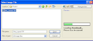
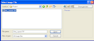
As you can see, it takes time to generate the thumbnail preview of the image. The bigger the image size, the longer it takes to generate the preview. You can switch off the preview by clicking on the 'Hide Preview' button on top right corner of the dialog box. Once you have switched it off, the button caption will change to 'Show Preview'. When you finish processing the big files, you can turn the preview on by clicking on it.


I often work with large tiff images and this feature saves a lot of time for me.