For the keyboard fans, who don't like working with menus and ribbons, there are several easy to use keyboard shortcuts inside ADR to make your life a lot easier. Some of those deserve a special mention for the fact that they are single key shortcuts. Using these shortcuts, the navigation options seem to be as easy as in AutoCAD, or even better. Here goes some of the single key shortcuts those caught my eyes at first sight.
R - Zoom Rectangle
F - Fit to Window
Q - Dynamic Zoom
H - Pan
PgUp - Next Page
PgDn - Previous Page
G - Length (Dimension)
N - Full Screen (Toggle)
I personally found the 'R' and 'F' shortcuts combination so terrific that it could easily beat the speed of Z+W and Z+E combination in AutoCAD. For a full list of ADR shortcuts, please refer to the help section inside the application. Unfortunately, I could not find any equivalent shortcut keys for DWG TrueView. If it's not available in TrueView, Autodesk should seriously consider incorporating it, atleast for the navigation options. For sure, these applications are going to be more and more popular in the future.
Thursday, May 21, 2009

Wednesday, April 15, 2009
How To Use Autodesk Design Review As Your Default Raster Image Viewer
Have you had a lot of headache in the past for viewing raster files those are not supported by windows built in image viewer applications? Don't worry, the solution is right under your nose. Apart from serving as an excellent review application, Autodesk Design Review can also be used as a raster image viewer. That means, you don't have to attach the raster images inside AutoCAD to view the contents. Instead, you can directly double click it on the explorer so that it opens directly in the Design Review application. Please make sure that you have done the following steps.
1. Goto Control Panel and double click on 'Folder Options'.
2. Goto the 'File Types' tab.
3. Locate the raster file extension inside the 'registered file types' list
4. If the extension does not exist, then click on 'New' to create a new one.
1. Goto Control Panel and double click on 'Folder Options'.
2. Goto the 'File Types' tab.
3. Locate the raster file extension inside the 'registered file types' list
4. If the extension does not exist, then click on 'New' to create a new one.
 5. Select the extension from the list and click on 'Change' button shown in the details section.

6. From the next popup window, choose 'Select the program from a list' option.
 7. Choose Autodesk DWF Application as the preferred application to open files with this extension. Also remember to check the 'Always use the selected program to open this kind of file' check box shown right under the list.

8. If everything is done properly, it will look as shown in the image below.

That's it. Repeat the same steps for other types of raster files. Once done, you don't have worry about it any more. Now you can goto explorer and double click those files to open it directly inside the Design Review application. I have configured mine to view file types like CAL, CALS, GP4, CG4, MIL, RST, PCT, PICT, TGA, RLS etc. (testing pending for some types). The best part of the story is that you can easily save this image as a DWF(x) file in order to send it to somebody for review purpose.
Autodesk Design Review is a wonderful review application with exciting features like '2D content comparison', 'PDF Support' etc. It's free and can be downloaded from the Autdesk Design Review site.
Sunday, January 25, 2009
Assigning Multiple Double Click Actions to Single Entity Type in AutoCAD
In the Unleash the Double Click Power post, you saw how to customize the double click action of an entity type to implement custom double click actions. Now we are going to see how we can implement different double click actions simultaneously on single entity type. Normally, we accomplish this by using Reactors or Events in the respective languages. But, we are not going to use any of these in our method. Rather, we will follow a tricky way to achieve the same result.
As an example, I will show you how to change the double click action of an 'Attribute Block'. Normally double clicking an attribute block shows the Enhanced Attribute Editor Dialog. We are going to change this to show either Enhanced Attribute Editor(_eattedit) or Edit Attributes dialog (_attedit) depending on certain condition. Let's say, when we double click on a title block named TITLE_BLOCK, it should display the Enhanced Attribute Editor dialog and for all other blocks in the drawing, it should display Edit Attributes dialog. The step by step configuration is given below.
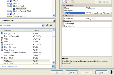
As an example, I will show you how to change the double click action of an 'Attribute Block'. Normally double clicking an attribute block shows the Enhanced Attribute Editor Dialog. We are going to change this to show either Enhanced Attribute Editor(_eattedit) or Edit Attributes dialog (_attedit) depending on certain condition. Let's say, when we double click on a title block named TITLE_BLOCK, it should display the Enhanced Attribute Editor dialog and for all other blocks in the drawing, it should display Edit Attributes dialog. The step by step configuration is given below.
- Open CUI and create a custom command with the following code inside the macro section of the command. If you don't know how to create a custom command, then refer to the 'Unleash the Double Click Power' post mentioned above. Replace the 'TITLE_BLOCK' inside the following code with your actual title block name.
^C^C(if (= (cdr (assoc 2 (entget (ssname (ssget "P") 0)))) "TITLE_BLOCK") (command "_eattedit")(command "_ddatte" )) - Drag and drop the custom command under the 'Attribute Block' section inside the Double Click Actions.
- Click on 'Apply' and close the CUI dialog.

That's it. Now if you double click on the title block, it will open the Enhanced Attribute Editor dialog and for all other attributed blocks, it will open Edit Attributes dialog. By the way, don't forget to take a backup of the default CUI files before you start experimenting with them.
Sunday, January 18, 2009
Quick Tip - A Shortcut for Closing Active Drawing
You already know that ALT+F4 can effectively be used to quit a running application in windows operating system. For those who don't know, pressing CTRL+F4 inside AutoCAD will close the active drawing without touching the application or other drawings already open over there. Though it's a more straight forward shortcut than the ALT+F+C, I would like to stick to the latter as it looks easier to me (May be because I am used to that). CTRL+F4 shortcut is not limited to AutoCAD, but it works well with almost all windows multi document interface (MDI) applications.
Sunday, January 4, 2009
My New Year Wish - An Intermediate AutoCAD Product for 2D Designing & Draughting
Why? Let's have a look at the existing product line. ie, Vanilla AutoCAD and AutoCAD LT. You might be able to find an answer from there.
AutoCAD LT: The lack of strong application programming interfaces makes AutoCAD LT really handicapped in the perspective of a Power User or CAD Administrator. You can not use any of your custom commands developed using AutoLISP/VBA/Dotnet/ObjectARX inside LT. The remaining option called DIESEL is only good enough to make small macros. Not only that; the number of commands are limited as compared to the full version.
Vanilla AutoCAD: Very powerful platform for 2D as well as 3D designing and modeling. The disadvantage is that it's loaded with comprehensive 3D modeling and rendering engines which are not at all used by the 2D user. Believe me; I have never used any of the 3D modeling or rendering features for the past 4 or 5 years for official purpose. That means the 2D users are carrying a burden over their shoulders and have been quite unnecessarily paying for the unwanted features. They could work much faster, if all those unwanted features were not loaded over there. The recent versions of AutoCAD show that it is more inclined towards 3D development than the 2D ones.
The need of the moment is an intermediate AutoCAD Product, which offers the power of Vanilla AutoCAD customization and 2D features minus all the 3D/rendering features with an attractive price tag. In that case, managers don't have to think twice at the time of purchase/upgrade of the product as they normally would do. As of now, we are forced to use Vanilla AutoCAD as we have in-house discipline specific menus and associated programs.
I am sorry to have started the New Year in a rebellion mood. But we really wish to see such a product available in the industry. Please note that the above views and opinions are my personal ones and those don't reflect the views or policies of the company I am working for. I take this opportunity to wish you a happy and prosperous new year. May the New Year make our dreams (including the CAD related ones ;-) come true...!! Many thanks to all you people for visiting my blog.
AutoCAD LT: The lack of strong application programming interfaces makes AutoCAD LT really handicapped in the perspective of a Power User or CAD Administrator. You can not use any of your custom commands developed using AutoLISP/VBA/Dotnet/ObjectARX inside LT. The remaining option called DIESEL is only good enough to make small macros. Not only that; the number of commands are limited as compared to the full version.
Vanilla AutoCAD: Very powerful platform for 2D as well as 3D designing and modeling. The disadvantage is that it's loaded with comprehensive 3D modeling and rendering engines which are not at all used by the 2D user. Believe me; I have never used any of the 3D modeling or rendering features for the past 4 or 5 years for official purpose. That means the 2D users are carrying a burden over their shoulders and have been quite unnecessarily paying for the unwanted features. They could work much faster, if all those unwanted features were not loaded over there. The recent versions of AutoCAD show that it is more inclined towards 3D development than the 2D ones.
The need of the moment is an intermediate AutoCAD Product, which offers the power of Vanilla AutoCAD customization and 2D features minus all the 3D/rendering features with an attractive price tag. In that case, managers don't have to think twice at the time of purchase/upgrade of the product as they normally would do. As of now, we are forced to use Vanilla AutoCAD as we have in-house discipline specific menus and associated programs.
I am sorry to have started the New Year in a rebellion mood. But we really wish to see such a product available in the industry. Please note that the above views and opinions are my personal ones and those don't reflect the views or policies of the company I am working for. I take this opportunity to wish you a happy and prosperous new year. May the New Year make our dreams (including the CAD related ones ;-) come true...!! Many thanks to all you people for visiting my blog.
Wednesday, November 19, 2008
Developing a Sine Wave Generator using DIECAL
In the last post, we saw how easiy we could accomplish complicated operations using DIECAL. Further to that, we are going develop a sine wave generator using a few lines of code. I know that you don't have a sine wave generator even in your wildest DIESEL dreams. But it is a really simple task using DIECAL. Once again, I am going to use points in order to make it simple. For generating sine wave, use the following macro.
*^C^C_setvar;userr1;$M=$(+,$(getvar,userr1),$(getvar,userr2))$(if,$(>=,$(*,$(+,$(getvar,userr1),$(getvar,userr2)),10),$(*,$(getvar,userr3),360)),^C)_Point;'CAL;[$(getvar,userr4)+$(+,$(getvar,userr1),$(getvar,userr2))/18,sin(10*$(+,$(getvar,userr1),$(getvar,userr2)))];
The above macro makes use of USERR1 to USERR4 system variables. The USERR1 and USERR2 values are automatically set by the set/reset macro (given below). USERR3 holds the value for number of cycles created and USERR4 is for X axis lag value (See the sample image). Use the following macro to set/reset initial values. When you run this macro, just follow the status bar messages.
^C^C_setvar;userr1;-1;;userr2;1;userr3;1;_modemacro;Enter number of cycles:;userr3;\userr4;0;_modemacro;Enter lag value for X axis:;setvar;userr4;\_modemacro;.;
The following image illustrates three sine waves gererated with a cycle value of 3 and X axis lag value 0 (Red) .22 (Green) and .44(Yellow).

*^C^C_setvar;userr1;$M=$(+,$(getvar,userr1),$(getvar,userr2))$(if,$(>=,$(*,$(+,$(getvar,userr1),$(getvar,userr2)),10),$(*,$(getvar,userr3),360)),^C)_Point;'CAL;[$(getvar,userr4)+$(+,$(getvar,userr1),$(getvar,userr2))/18,sin(10*$(+,$(getvar,userr1),$(getvar,userr2)))];
The above macro makes use of USERR1 to USERR4 system variables. The USERR1 and USERR2 values are automatically set by the set/reset macro (given below). USERR3 holds the value for number of cycles created and USERR4 is for X axis lag value (See the sample image). Use the following macro to set/reset initial values. When you run this macro, just follow the status bar messages.
^C^C_setvar;userr1;-1;;userr2;1;userr3;1;_modemacro;Enter number of cycles:;userr3;\userr4;0;_modemacro;Enter lag value for X axis:;setvar;userr4;\_modemacro;.;
The following image illustrates three sine waves gererated with a cycle value of 3 and X axis lag value 0 (Red) .22 (Green) and .44(Yellow).

Thursday, November 13, 2008
DIECAL - It's DIESEL Enhanced with a Mathematical Engine
In the last post I mentioned that I could come up with some better posts after the vacation, with the help of a refreshed mind. Hope this post justifies my words.
The absence of a strong mathematical engine inside DIESEL has troubled most of us in the past. We are going to overcome this limitation by mixing up DIESEL with the command line calculater. It should work in AutoCAD LT as command line calculator has been included in LT2009.If you compare, DIECAL capabilities are far better than DIESEL. Using DIECAL, you can do vector calculations, access various numeric functions which are not available in DIESEL and can do so many other things. If you are not convinced, here is a sample macro to draw a sphere by placing points across the surface of a sphere.
*^C^Csetvar;userr1;$M=$(+,$(getvar,userr1),$(getvar,userr4));$(if,$(>=,$(getvar,userr1),360),setvar;userr2;$
(+,$(getvar,userr2),$(getvar,userr5));setvar;userr1;0;)_Point;'CAL;[$(getvar,userr3)
<$(+,$(getvar,userr1),$(getvar,userr4))<$(getvar,userr2)];$(if,$(>,$(getvar,userr2),270),^c)
This macro uses USERR1 to USERR5 system variables to store values. The USERR1 and USERR2 system variable values are handled by the above macro. The USERR3 system variable stores the radius of the sphere, USERR4 holds the angle between the horizontal points and USERR5 holds the angle between vertical points. These values can be set/reset using the following macro. When you run this macro, just follow the instructions shown in the status bar.
^C^C_setvar;userr1;0;;userr2;90;_modemacro;Enter sphere radius:;userr3;\_modemacro;Enter angle between horizontal points:;userr4;\_modemacro;Enter angle between vertical points:;userr5;\_modemacro;.;
Please remember to run this macro to set/reset values before using the main macro.The first macro makes use of the Spherical Coordinate System point format entry to place points across the surface of the sphere.Please note that the CAL command has to be invoked transparently ('CAL) in the macro in order to output the result of calculation to the active command. It's my lack of knowledge in mathematics that prevents me from showing off a powerful application to exihibit the true potential of DIECAL. Those who know trigonometry and vector algebra will really enjoy this method. Following are some sample spheres made using different radius and angle values.

Point Sphere - Top View
The absence of a strong mathematical engine inside DIESEL has troubled most of us in the past. We are going to overcome this limitation by mixing up DIESEL with the command line calculater. It should work in AutoCAD LT as command line calculator has been included in LT2009.If you compare, DIECAL capabilities are far better than DIESEL. Using DIECAL, you can do vector calculations, access various numeric functions which are not available in DIESEL and can do so many other things. If you are not convinced, here is a sample macro to draw a sphere by placing points across the surface of a sphere.
*^C^Csetvar;userr1;$M=$(+,$(getvar,userr1),$(getvar,userr4));$(if,$(>=,$(getvar,userr1),360),setvar;userr2;$
(+,$(getvar,userr2),$(getvar,userr5));setvar;userr1;0;)_Point;'CAL;[$(getvar,userr3)
<$(+,$(getvar,userr1),$(getvar,userr4))<$(getvar,userr2)];$(if,$(>,$(getvar,userr2),270),^c)
This macro uses USERR1 to USERR5 system variables to store values. The USERR1 and USERR2 system variable values are handled by the above macro. The USERR3 system variable stores the radius of the sphere, USERR4 holds the angle between the horizontal points and USERR5 holds the angle between vertical points. These values can be set/reset using the following macro. When you run this macro, just follow the instructions shown in the status bar.
^C^C_setvar;userr1;0;;userr2;90;_modemacro;Enter sphere radius:;userr3;\_modemacro;Enter angle between horizontal points:;userr4;\_modemacro;Enter angle between vertical points:;userr5;\_modemacro;.;
Please remember to run this macro to set/reset values before using the main macro.The first macro makes use of the Spherical Coordinate System point format entry to place points across the surface of the sphere.Please note that the CAL command has to be invoked transparently ('CAL) in the macro in order to output the result of calculation to the active command. It's my lack of knowledge in mathematics that prevents me from showing off a powerful application to exihibit the true potential of DIECAL. Those who know trigonometry and vector algebra will really enjoy this method. Following are some sample spheres made using different radius and angle values.
 Point Sphere - 3D View

Point Sphere - Top View
Due to the presence of 3D elements, I am not quite sure whether the LT people can use the above macro. But they can surely develop a lot of advanced macros using DIECAL. To get an idea of things that can be done using DIECAL, refer to command line calculator section in AutoCAD help. Now even AutoCAD LT seems to be really unlimited. Doesn't it?
Subscribe to:
Posts (Atom)


